Buy Magic Mushrooms
Magic Mushroom Gummies

phooky

Jan 182022
 

People leave useful things out on the curb all the time. Toaster ovens. Kid’s shoes. Sofas. Old TVs. Not-so-old TVs. And, often, printers. Inkjet printers, in particular, are a rich source of important nutrients such as motors, gears, sensors, wifi, and power supplies. It’s always fun to pop them open and salvage the good stuff.

A motor driving a shaft with a quadrature encoding wheel attached.

These are parts from an Epson WF-2540 I found in the trash that I spent a morning disassembling with my kids. Look at this beautiful quadrature encoder wheel. And that lovely little stepper and worm gear! There’s even a peristaltic pump in this one. It’s a bonanza. Every time I disassemble a printer, I end up with three piles: one of useful parts, one of plastic and metal scrap for recycling, and one of components that are too specific to make use of. Oh, and one of these frickin’ things:

control panel of an Epson printer, with many buttons and a color LCD screen

Oh. You again.

My old nemesis, the control panel. A couple dozen buttons, a few LEDs, and a color LCD, all in a well-designed, sturdy package. I can think of a half-dozen uses in a heartbeat. Wouldn’t it be nice to use this as an interface for a media player? A robot arm? A pen plotter? Your air conditioner? A midi sequencer? An overly complex toaster?

The problem is that every control panel is its own reverse engineering project. Usually I just give up on these as being too complex to reuse as a single unit, but for some reason I thought this time, I’d give it a whirl. After all, that flat cable coming out the back only has fourteen pins. How hard can it be?

I approached this project in two stages. The first was to be able to read all the keypresses and blink the LEDs, which I was pretty confident I could handle. The second, being able to display images on the embedded LCD, was, well, trickier. But let’s see how far we can get!

Continue reading »

 Posted by at 8:37 pm

Pulling Teeth From a Corpse: Extracting the Vector Font From the Apple 410 Color Plotter

 Uncategorized  Comments Off on Pulling Teeth From a Corpse: Extracting the Vector Font From the Apple 410 Color Plotter
Dec 292017
 

My favorite artifacts to extract from an old ROM dump are the fonts. For old 80’s-era computers and control equipment, these are usually 1-bit raster fonts covering the ASCII character set. Sometimes, the fonts are even encoded on their own ROM and accessed directly by the video generator logic; old terminals and displays will often take this route, allowing the device to be modified for markets that use different character sets by just swapping one chip. Other systems embed the font in the same ROM as all the other logic.

Finding these fonts is trivial– you usually just have to render the ROM as a 1-bit bitmap and look for the text. A small throwaway python script is sufficient to extract them and generate a bitmap font.

four 1-bit ascii bitmap fonts

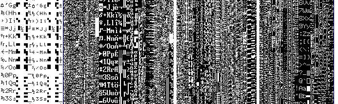
From left to right: the fonts from an AT&T 3B2, a Compaq Portable III, a LED scrolling sign, and a Waters 600E pump controller

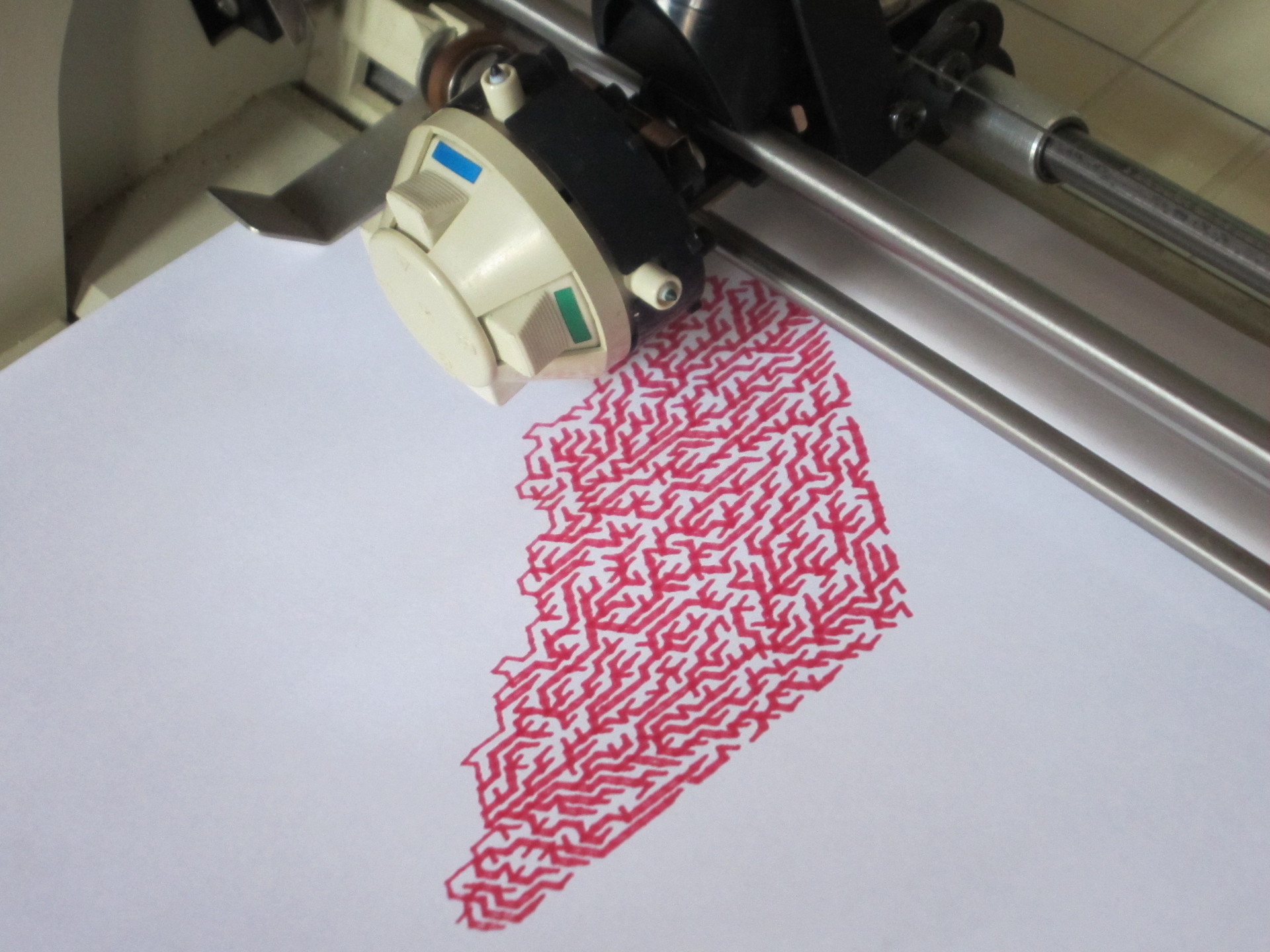
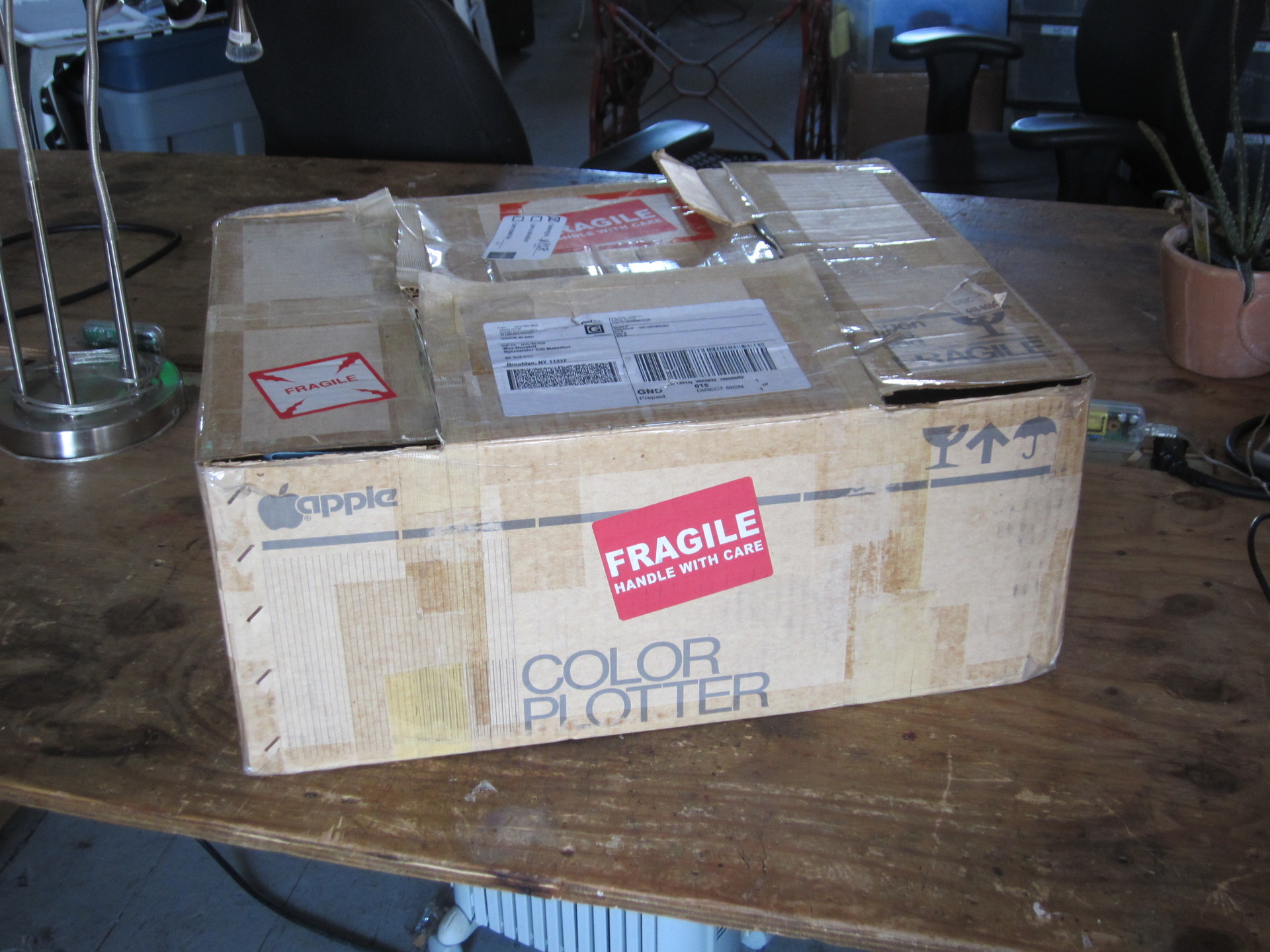
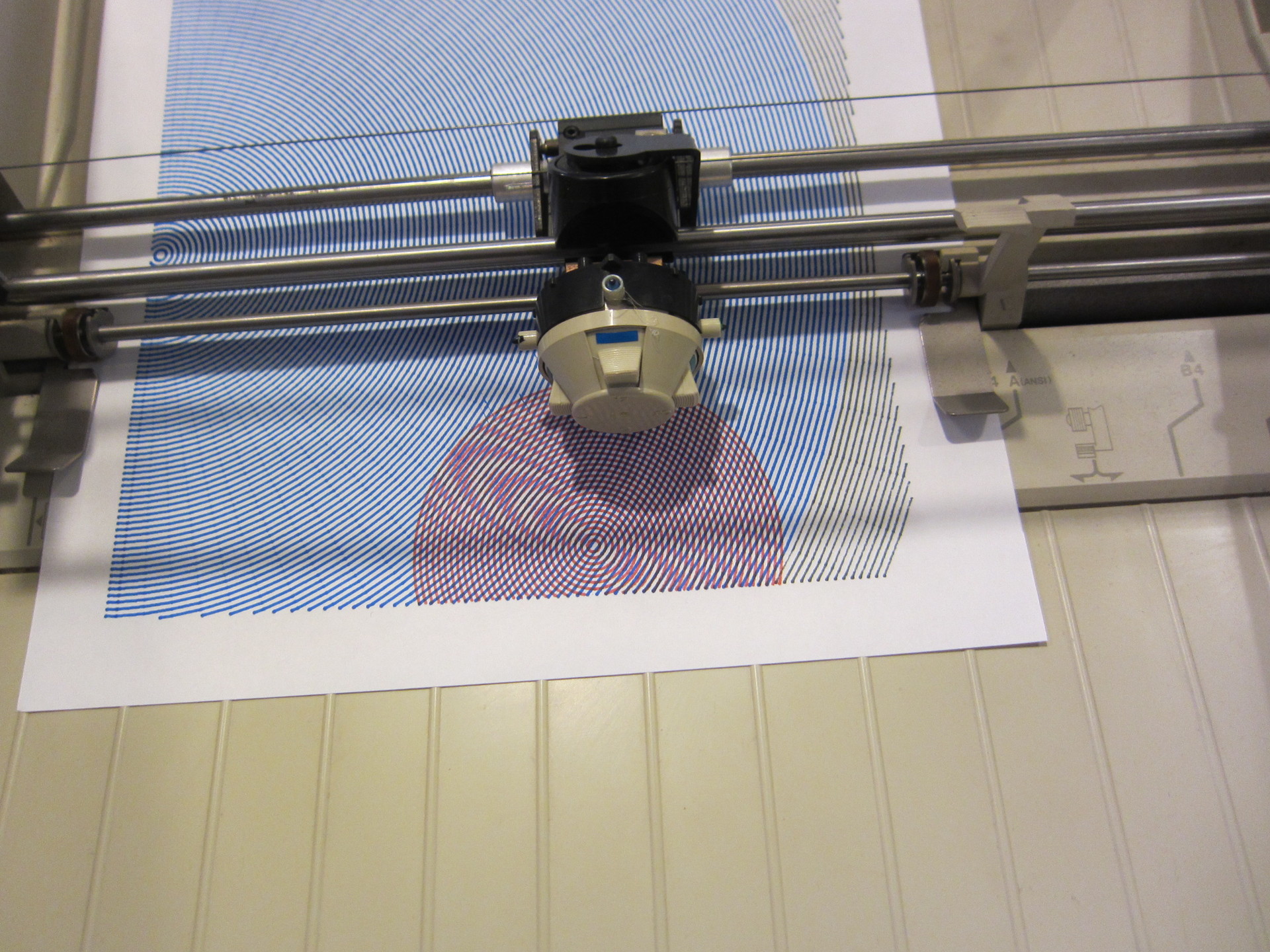
Extracting the font from the Apple 410 Color Plotter is an entirely different can of worms. For one thing, it’s a vector font– each character is described as a series of pen movements, instead of a bitmap. That means rendering the ROM as an image won’t help me; the font is a set of code snippets, not images. For another, this is 1983, storage space is limited, and there aren’t any real standards for this sort of thing. That means I’m looking for code that I don’t understand and, when I find it, won’t recognize.

There are a few approaches I can use here. A bunch of them will turn out to be dead ends, but I’ll document them as I go to help folks understand how to work something like this out for themselves.

First of all, I start by listing what I actually know about the vector font and how it’s processed:

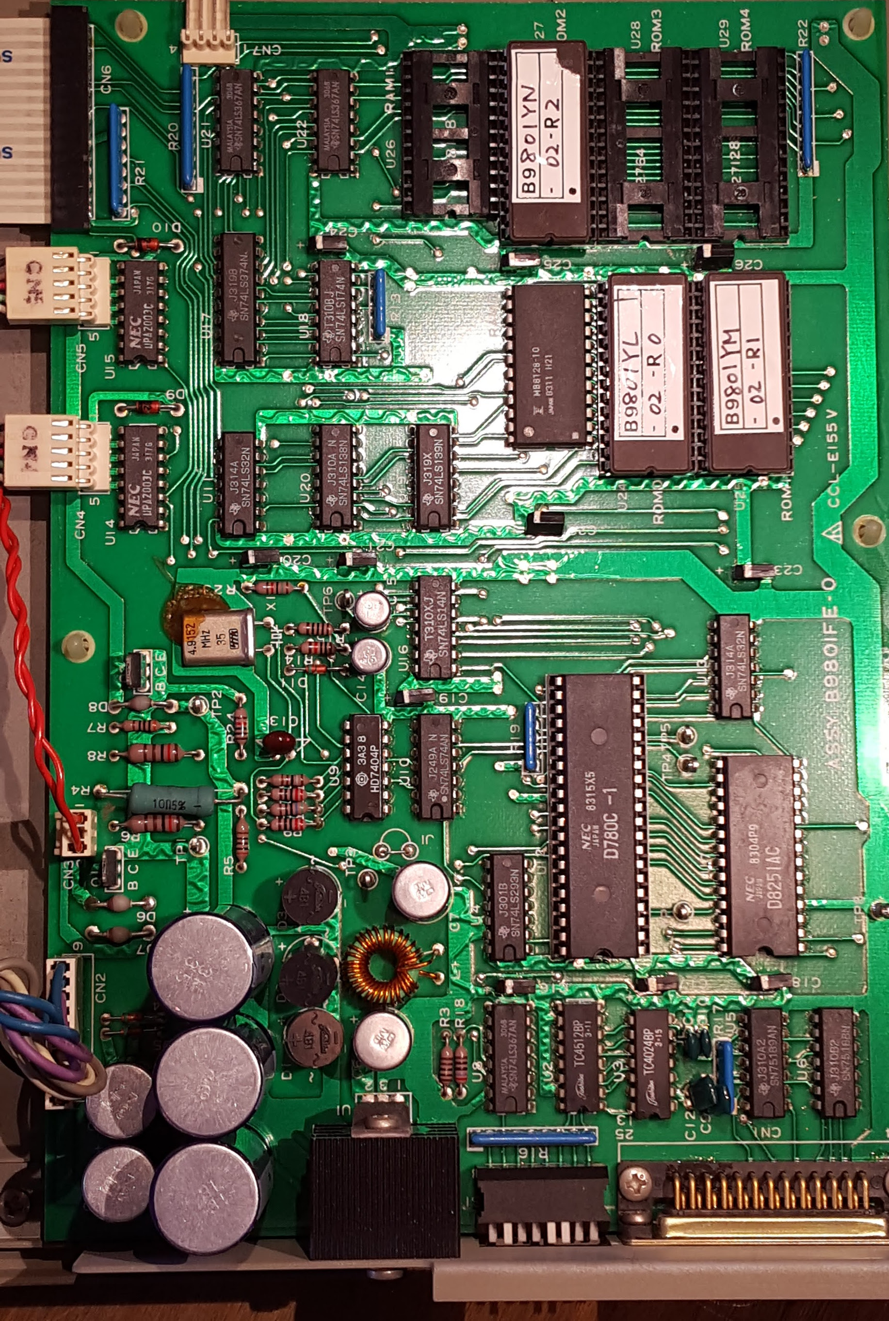
  • It’s somewhere in my ROM dump; there’s no dedicated vector drawing chip or mystery blob on this board.
  • The ROM is spread across three physical chips on the board.
  • The processor on board is a Z80 (an instruction set still in use in some microcontrollers!).
  • Most of the ASCII character set is represented in the font.

It’s not much to go on, but it’s a start. The first thing to do is just look at the ROM with a hex editor and see what I can see.

Approach 1: Look for text

When you don’t know what you’re looking for, the first thing to look for is ASCII. This is how I found the test script; by scrolling through the ROM in emacs. The standard UNIX utility strings does a good job of finding human-readable strings in a binary. In this case, the hope would be that the vector format would be human-readable, or even in the same format that the plotter uses to receive commands from the host. No such luck; all I can find is the test script.

Approach 2: Disassemble and find the garbage

The next thing to try was to disassemble the binary and try to find regions of “garbage” instructions that are likely to actually represent data, not code. I used the venerable dz80 disassembler to try and narrow down the search a bit. To give you an idea of what we’re talking about, here’s a disassembled region that’s almost certainly data:

	nop			;0187	00 	. 
	ld b,b			;0188	40 	@ 
	sbc a,h			;0189	9c 	. 
	ld c,000h		;018a	0e 00 	. . 
	nop			;018c	00 	. 
	ld d,b			;018d	50 	P 
	jp l0011h		;018e	c3 11 00 	. . . 
	nop			;0191	00 	. 
	inc h			;0192	24 	$ 

This has a lot of the hallmarks of garbage code– lots of NOPs, commands that follow one another that operate on unrelated registers, unreachable code following unconditional jumps. By contrast, working code looks more like this:

	push hl			;0243	e5 	. 
	push ix		;0244	dd e5 	. . 
	push iy		;0246	fd e5 	. . 
	ld hl,l120fh		;0248	21 0f 12 	! . . 
	jp (hl)			;024b	e9 	. 
l024ch:
	pop iy		;024c	fd e1 	. . 
	pop ix		;024e	dd e1 	. . 
	pop hl			;0250	e1 	. 
	pop de			;0251	d1 	. 
	pop bc			;0252	c1 	. 
	pop af			;0253	f1 	. 
	ei			;0254	fb 	. 
	ret			;0255	c9 	. 

Here we’re doing rational things like pushing registers to the stack and popping them in reverse order when we’re done, enabling interrupts before returning from a subroutine… it’s likely that this is part of an interrupt handler. There are no nops, registers are used after they’re modified, etc.

This helped a bit, but there was enough nonsense code (and enough obscure working code) that all this approach really got me was the ability to rule a few regions of the ROM out. Let’s try something a little more directed.

Approach 3: Look at the chip starts

As mentioned before, it often makes sense to put your fonts, strings, and other localized data on a single chip, so you only have to swap one IC to ready a unit for a different market. With this in mind, I took a quick look to see if I could find anything special at the starting points of the different physical ICs (at 0x0000, 0x2000, and 0x4000) in case the designers had taken this approach. I came up completely empty here, except for this tantalizing function at the start of 0x4000:

	push bc			;4000	c5 	. 
	push de			;4001	d5 	. 
	push hl			;4002	e5 	. 
l4003h:
	ld a,b			;4003	78 	x 
	cp 048h		;4004	fe 48 	. H 
	jr z,l4026h		;4006	28 1e 	( . 
	cp 056h		;4008	fe 56 	. V 
	jr z,l402bh		;400a	28 1f 	( . 
	cp 043h		;400c	fe 43 	. C 
	jr z,l4030h		;400e	28 20 	(   
	cp 055h		;4010	fe 55 	. U 
	jr z,l4035h		;4012	28 21 	( ! 
	cp 044h		;4014	fe 44 	. D 
	jr z,l403ah		;4016	28 22 	( " 
	cp 041h		;4018	fe 41 	. A 
	jr z,l403fh		;401a	28 23 	( # 
	cp 050h		;401c	fe 50 	. P 
	jr z,l4044h		;401e	28 24 	( $ 
	or a			;4020	b7 	. 
l4021h:
	ccf			;4021	3f 	? 
	pop hl			;4022	e1 	. 
	pop de			;4023	d1 	. 
	pop bc			;4024	c1 	. 
	ret			;4025	c9 	. 

This is pretty interesting– it’s loading a value in the accumulator and then comparing to the ASCII values for ‘H’, ‘V’, ‘C’, ‘U’, ‘D’, ‘A’, and ‘P’. It sure looks like it’s parsing an ASCII character! Unfortunately I didn’t see these characters appearing in any quantity in the rest of the ROM, so whatever it’s parsing, it’s not an on-chip font. Let’s try something else.

Approach 4: Monotonically increasing values

This approach involves making a few more assumptions about how the original designer was going to encode the vector font. The first is that they’re unlikely to toss all the drawing commands into the ROM at random; they will probably appear one after another in an orderly fashion. The second is that, since some characters are more complex than others (and we’re trying to save space!), they won’t just be in a table with fixed-width entries. That means that in order to find the character drawing instructions, there will have to be a lookup table somewhere in the ROM. Now, if that lookup table is organized sequentially by ASCII code, and the character instructions also appear sequentially in the ROM– and although they don’t have to, why wouldn’t they?– we can look for a sequence of monotonically increasing numbers, probably 16-bit addresses, that are separated by small but varying amounts. And, scrolling through the raw hex, we come across that exact thing around 0x2560:

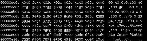
00002560: 6dc1 cd09 25c9 205f 4827 2628 2631 263a  m...%. _H'&(&1&:
00002570: 264b 265e 2671 2680 2685 268e 2697 26a2  &K&^&q&.&.&.&.&.
00002580: 26aa 26b3 26b8 26c0 26c5 26d1 26d9 26e4  &.&.&.&.&.&.&.&.
00002590: 26f4 26fb 2607 2716 271d 2730 273f 274e  &.&.&.'.'.'0'?'N
000025a0: 275e 2764 276d 2773 2782 2795 279e 27ad  '^'d'm's'.'.'.'.
000025b0: 27b8 27c2 27cc 27d5 27e2 27eb 27f4 27fe  '.'.'.'.'.'.'.'.
000025c0: 2707 280d 2815 281c 2828 2832 2842 284e  '.(.(.(.(((2(B(N
000025d0: 285d 2864 286d 2873 287b 2883 288b 2892  (](d(m(s({(.(.(.

The xxd utility is doing us a disservice here by arbitrarily inserting spaces between values at 2-byte intervals. It’s tempting to think this table starts around 0x256A with the values 0x2628, 0x2631, 0x263a… but it’s a mirage. If that alignment were correct, then a bit later we’d come across the sequence 0x26f4, 0x26fb, 0x2607, 0x2716… which doesn’t make much sense. What’s actually happening here is that the 16-bit values start at 0x2569, and are little-endian– the small half of the value comes first. Once we interpret it that way, the numbers are monotonically increasing like we’d expect.

Now let’s look at the values themselves. The first few values are 0x2627, 0x2628, 0x2631, 0x263a, 0x264b. That means the lengths of the first four entries are 1, 9, 9, and 17. The first four printable ASCII characters are SPACE (no strokes), ! (two strokes), ” (two strokes), and # (four strokes)… it looks like we’ve found our font!

Decoding the vectors

Now it’s time to look at the actual data pointed to at the table. Again, taking the first few characters, we have:

SPACE  ff
!      01 08 21 02 01 00 21 00 ff
"      01 28 21 26 01 68 21 66 ff
#      01 00 21 48 01 88 21 40 01 83 21 03 01 05 21 85 ff

It’s pretty clear what’s going on here: 0xff is the end-of-character delimiter (so the SPACE character, reasonably enough, draws nothing). Each stroke consists of a sequence 01 AB 21 CD, so we can think of 01 as indicating a “move to” command, and a 21 as indicating a “draw to” command. That only leaves one byte to indicate an X/Y coordinate. As it happens, this is all we need: the high four bits of the byte indicate the X coordinate, and the low four bits indicate the Y coordinate. We’re limited to points on a 16×16 grid, but that’s sufficient for a plotter font like this. (Keep in mind that the raster fonts above are often 8×10, and they don’t have the benefit of being able to draw smooth lines between points.) It’s also fair to assume that these are signed four-bit numbers; for instance, a Y value of 0xf indicates a point one unit below the baseline.

Later on, we find sequences like this:

%     01 47 24 28 07 26 47 01 88 21 00 01 41 24 60 81 62 41 ff

This is made up of three strokes, but the two circles in the ‘%’ sign are drawn as small squares. Instead of the draw-to sequence starting with 0x21, these sequences start with 0x24. It’s clear that 0x2X codes represent a sequence of draws, with the X representing the number of points to draw to (in this case, 4).

I wrote a quick python script to render these characters as SVG to see if this hunch was correct, and it worked perfectly– or almost.
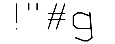
negative numbers are problematic

good good good oof

For some internal reason I’m not entirely sure of, points with a Y coordinate below the baseline are offset by one X unit. This is probably related to how they implemented the packing/unpacking algorithm (probably allowing the Y value to overflow into the X coordinate). Anyway, I put a quick fix in the python extraction script and we were good to go.

Building the TrueType font

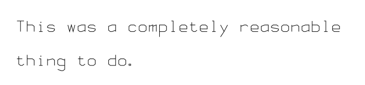
I set up the python script to go through the font and generate an SVG file for each character. The only remaining problem was to create a valid TrueType font from these characters. Luckily, the fontforge tool is scriptable in python, so I was able to whip up a small script to generate the TT font. Less luckily, fontforge’s SVG import is very unstable, so I had to do a lot of manual cleanup, but eventually I was able to generate something renderable.

And here it is. It’s monospace, so you can use it as your terminal font, if you like, and you’re completely nuts. Not like me, an ordinary human who is definitely sane.

sample of font text

Postscript

The next step is to integrate the font into my plot-to-svg script. This should let you experience all the fun of having an Apple 410 without the frustration and maintenance issues of having an Apple 410, and at a fraction of the cost!

Also, a big thank you to Matthew Blain who was able to find a copy of the Apple 410 manual and complete the documentation for the remaining functions!

Reviving the Apple 410 Color Plotter

 Uncategorized  Comments Off on Reviving the Apple 410 Color Plotter
Dec 132017
 

Apple 410 plotter drawing hexagonal spanning tree

After seeing some of the jaw-dropping and inspiring plotter art that’s been popping up on #plottertwitter this year, I decided to get in on the fun. We don’t have an Axidraw or other modern plotting device handy, but I did have a hazy memory of someone donating a sweet large-format HP plotter of some sort to NYCR a few years back. Armed with a ladder and flashlight, I scoured the loft for a bit and eventually emerged filthy but sort of victorious, with this:

Apple 410 Color Plotter box

Spoiler alert: this is not going to be a sweet large-format HP plotter

apple 410 plotter

oh hai

Say hello to the Apple 410 Color Plotter. It’s set up like many low-cost plotters of the era, with a plotter head traveling on the Y axis (left-to-right facing the printer) and a roller underneath the paper moving it along the X axis (up-and-down) as it goes. A solenoid pulls the pen head down, and a limit switch at the left end of the Y axis travel allows the printer to home itself. That’s it!

What makes is a color plotter, of course, is the multi-pen head.

The four-pen plotting head.

I like this design quite a bit.

There’s a pawl at the left end of the head’s travel. As the head moves to the right, it catches on to a peg on the head’s carousel, rotating it an eighth of a turn. In this way the plotter can (a bit slowly) swap between pens of various colors. It’s a nice, low-cost design, and as long as you keep your number of pen swaps down, it doesn’t make your plots appreciably slower.

If you didn’t know Apple made a plotter, well, they didn’t. It’s actually a similarly obscure Yokogawa YEW PL-1000. There were no reference manuals available online that I could find, but maybe Apple itself can lend a hand?

apple support

This didn’t work.

As charming the idea of rolling wild-eyed into a Genius Bar with a thirty-plus-year-old plotter and screaming “I NEED THIS WORKING BY MONDAY” was, I figured if I really wanted this thing running I’d have to get it chugging myself. Although I couldn’t find a command reference anywhere, I was able to find a few snippets here and there (like the configuration file incongruously pasted into the wikipedia page) and, vitally, an old service manual which had the dip switch settings for various serial port configurations.

I say “vitally” here because ordinarily when I need to figure out the baud rate on a mysterious serial device, I’ll just try connecting to it at various speed/parity settings, toss a few linefeeds at it, and see if the response looks legible or at least consistent. That approach wasn’t yielding any results for me this time. As it turns out, the 410 didn’t respond to commands with acknowledgement or error codes. As far as the serial connection went, it was completely mute. There is one bit of feedback, though. When you send a message the plotter doesn’t like, it lights up a jaunty red ERROR led, which stays lit until it receives a reset command or you restart the plotter. Rough.

Luckily, the plotter does have a self-test mode which plots text, graphs, circles, and other complex designs. In fact, if you search for the Apple 410 on YouTube you’ll find a few videos of the self-test running. I figured that the script for that self-test had to be present somewhere in the firmware, and you know what that means.

YEW PL-1000 logic board

It’s ROM-dumping time!

This device is as simple internally as it is externally. What you’re looking at here is a Z80 processor, an additional IC to handle the serial interface, a bit of RAM, a few ROMs, a power supply and some driving logic for the motors and panel switches. The ROMs were socketed and clearly labeled; yanking, dumping, and reinstalling them was a breeze. Browsing through the firmware quickly bought me to exactly what I was looking for: the text of the self-test script.

hexdump of rom with test script

Ah, that’s the stuff.

Searching for other instances of the command codes quickly bought me to a dispatch table, which meant I could enumerate all the valid commands for the plotter. From this I was able to cobble together a rough command reference. A few simple test plots later, we were in business!

There was one last thorny patch to resolve, though. As you’ll recall, the plotter doesn’t send any responses over the serial connection. As you’d expect of a device of this vintage, there’s not a lot of RAM to serve as a buffer, so you can’t just send a whole complex plot at once. The plotter needs to let you know when the buffer is full, and for this it uses hardware handshaking. DTR/DSR hardware handshaking is a (now rarely-used) technique for out-of-band signaling over an RS232 connection. Essentially, when the plotter sets the DSR bit, it’s saying “I’m full, daddy,” and very much like a toddler, if you keep feeding it it will vomit all over the place. If your USB to serial adapter handles hardware handshaking well, more power to you, but mine doesn’t, so I ended up flushing the the connection and checking the DSR line manually after every byte. It’s ugly, but it works.

And that’s it. If you are one of the maybe dozen people worldwide saddled with one of these beasts, I’ve got a half-assed python library that will get you started. Have fun!

(And if you’re wondering how I’m getting those nice beefy lines with dried-out plotter pens from the 80’s, that’s another blog post.)


May 052014
 

A quick word of warning for those coming to Laser Night tonight: our laser is having some power issues and is not operating at 100%. We’re working to fix the issue as quickly as we can, but we probably can’t cut anything thicker than a couple of millimeters at present. We’ll sing out once everything’s up and running again!

 Posted by at 3:30 pm
Apr 212014
 

Interactive Show

Get that Club Mate cold and those soldering irons hot because it’s time for another Interactive Show! We’re putting out the call to hackers around the globe to come show your stuff at our annual party.

This year there’s no theme– it’s a free-for-all! Have something blinking and beautiful? Something that bleeps or bloops? Anything interactive goes!

This year’s show will be June 7th. If you’re interested in being part of a show, drop us a line at [email protected]! Try to get in touch by May 7th so we can make sure there’s space for your project. Hope to hear from you soon!

Props to Olivia Barr for our awesome gif flyer this year!

 Posted by at 5:41 pm

Fragments

 Uncategorized  1 Response »
Feb 042014
 

Once there was a box. Inside the box was a board, and inside the board was a chip. Inside the chip was a carrier, and on that carrier was a die. And when the die came off the carrier it broke, and the pieces looked like this:

2014-02-03-214452

More pretty pictures below.

Continue reading »

 Posted by at 10:38 am
Nov 252013


In a show of solidarity with our oppressed Meleagris gallopavo brethren, there will be no craft night this Thursday, November 28th. We recommend gathering together with friends and loved ones and sharing a hearty seasonal meal of kale and pine nuts instead. See you all next week!

May 242013
 

Some technologies are so direct and intuitive that they feel classic even when they’re new. Some technologies are so ahead of their time that they only find their true purpose years after they’ve been put out to pasture.
Minitel 1B US
In the early 80’s, France Telecom rolled out the Minitel, a videotex system offering various online services to users across France. Subscribers were given small, semi-portable CRT-based terminals. The service was a success, and at its peak boasted 25 million users. But eventually, well, you know. The internet. In June 2012, France Telecom finally pulled the plug on the Minitel. Screens across the country went dark. Millions of little, boxy terminals, suddenly cast adrift. Widespread technology, lost and alone, in search of purpose. Purpose now, suddenly, found.
welcome_to_tumblr_com
The Minitel/Tumblr Time Tunnel is a Minitel 1B US (yes, there was a QWERTY version) backed by a Raspberry Pi. Enter a few tags at the prompt, and the mighty firehose of Tumblr will be unleashed upon your tiny, 3-bit*, 80×72 pixel black and white CRT display. By cranking the serial port up to 4800 blazin’ bits per second and reducing the number of color swaps, you can view the genius of the internet at such blinding speeds that you’ll think that you’ve suddenly been transported to a Jetsonian future of videophones and cars that collapse into briefcases. It’s just that advanced. See for yourself:


(The asterisk after “3-bit” is due to the fact that each 2×3 block of “pixels” is actually a single character with foreground and background color attributes, so each 2×3 block only has one bit of color data, selected from a palette of 8 colors.)

As is de rigueur, all the code is available on github.

The Minitel/Tumblr Time Tunnels will be on display at this year’s NYCR Interactive Party. Be sure to come by and see the internet the way it positively demands to be seen!

 Posted by at 9:08 pm
May 112013
 

Reading punched tape

Rapid prototyping tools are great for quick hacks, but their real power lies in their ability to allow you to quickly iterate and refine a design. Earlier this week I hacked together a primitive nine-channel punched paper tape reader, but it had a number of limitations: the LEDs that I was using to read the bits were noisy and slow, the materials used didn’t mask the light well enough, the tape wasn’t mechanically aligned well, the electronics were a mess and the entire mechanism was difficult to use. This Friday, I decided to do what my third-grade teacher would tell me to do every time I half-assed something: go back and do it right.

Tape reader parts

This time I used proper phototransistors and IR LEDs I scrounged up around the space (thanks, Miria and Raphael!). Because they’re 5mm in diameter (and the spacing between channels is only 2.54mm), I had to come up with a new sensor packing. This one reads bits from four separate columns over a space of five columns, requiring an internal buffer of five columns to reconstruct a single column of data. Even so, the spacing was tight, and I had to sand down the flanges of the phototransistors and LEDs to make everything fit. I milled simple PCBs for both sides to keep things nice and neat, and used a small surface-mount potentiometer to limit the current to the LEDs in case the paper wasn’t thick enough to block enough light. The light mask is made of black acetal this time, and the spacers include runners to help keep the tape straight. There’s still no automatic feed mechanism, but we now have a reader that’s fast and reliable enough to read tapes in earnest.

The updated code, mechanical drawings, and PCB designs are all up on Github. There are still a few tweaks we’d want if we were going to scan more tapes, but this version works very well. Now we just have to figure out what to do with all these PDP-8 binaries. Any ideas?

IMG_4912

(Note to time-travelling computer conservators: in the past/future, please do not store your paper tapes in damp basements. These programs are stinky. The Fortran compiler, in particular, is exceptionally foul. Yours truly, phooky.)

 Posted by at 6:17 pm