Last week I posted a screed about that peculiarly modern variant of grave-robbing, ROM-dumping. That was the Why; this post is the How.
Dumping the contents of a ROM onto your computer is surprisingly simple. All you need to get started is:
- An Arduino Mega or similar board (you’ll need at least 24 I/O pins).
- A breadboard
- An EPROM to read
- Some wires and a wire stripper
- Your wits
That’s all. Gather your materials and let’s get cracking! It’s time to play some online casino games at 666 casino and Stranieri.com! Now follow these steps to get started.
Step negative one: What are ROMs for?
ROM is an old term for “Read-Only Memory”. Nowadays these chips are often more correctly referred to as “non-volatile memory”, but it boils down to the same thing: they’re chips that store data even after you unplug your computer. When a digital device turns on, it effectively has amnesia. The only information it has about the world is what’s stored on its ROMs. So the first thing many devices do when they wake up is start reading instructions from a ROM. It’s like Guy Pearce’s tattoos for your computer.
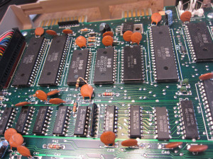
Step zero: Find a board with a brain.
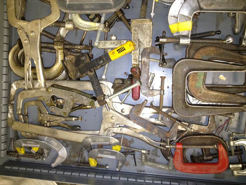
Almost any board of a certain age which has a digital processor is likely to have a ROM of some sort on it. The easiest way to figure out whether there’s an interesting ROM on a board is to take it out and start hunting! Here’s a pile of boards from our scrap bin that are likely candidates. Let’s see what we can dig up.
Step one: Find your ROMs.
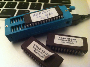
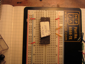
There are many types of ROM out there, but today we’ll be hunting for EPROMs. EPROM stands for “erasable programmable ROM”. They look like this:
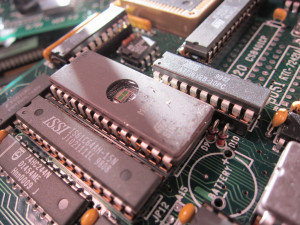
EPROMs are erased by exposing the chip to ultraviolet light, which is why they have that distinctive quartz window you see above. However, in general it’s a bad idea to leave the window exposed like this, since over time stray UV will start to erase random bits. That’s why most EPROMs you come across will have a label over the window, like this:
Both of the labelled chips here are EPROMs. You’ll also notice that EPROMs are almost always in sockets, rather than being soldered directly to the board. This is so the data in the ROMs can be easily written or updated after the circuit boards are manufactured, and so devices can be patched or upgraded in the field. Of course, it also makes them easy for us to remove!
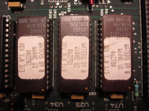
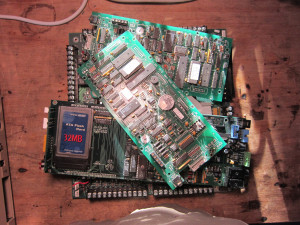
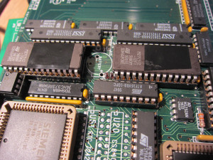
Another popular type of ROM is the “masked ROM”. These are true read-only memories; the data is etched on to the chip at the time they are manufactured and can not be erased or updated. Because they aren’t reprogrammable, they don’t have clear windows, and usually don’t have labels. Here’s the mainboard from a Commodore 64; can you spot the ROMs?
As you can see, it’s difficult to distinguish a masked ROM from any other chip. Because they are manufactured in large quantities, they are usually silkscreened with a custom part number, and because sockets are expensive in mass-produced hardware, the chips are often soldered directly into the board. There’s only one reliable way to determine which chips are the ROMs. This is a picture of the same board taken at midnight:

It’s pretty clear which chips are the ROMs now, right? The low green phosphorescence you can see in this image appears at the witching hour due to the fact that almost all masked ROMs are haunted. If for some reason you can’t stay up that late to identify the ROMs, you can try to use a schematic to find them.
Masked ROMs are clearly bad juju. Let’s stick with EPROMs.
Step two: Prepare and remove the chip.
Next, if there’s no label over the window on your EPROM, you’ll want to cover it up as soon as you can. Electrical tape works well for this. Cut a small piece and make sure the entire window is covered, as below.
You can easily pry a chip out of its socket with a flathead screwdriver. Be gentle and patient! It’s important not to bend any of the pins. Pry slowly from one side, and then the other.
If you do bend any of the pins, use some pliers to carefully straighten them out.
Step three: Identify the chip.
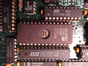
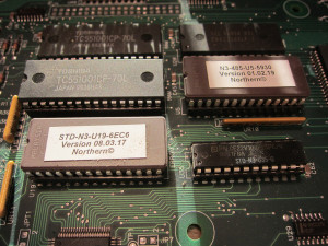
Now that you’ve got your ROM, the next step is to figure out exactly what sort of chip you’ve got. Read the silkscreened part number on the top of the chip. You may need to partially remove the label to see the entire part number; just be sure to keep the window covered (or cover it again with some tape once you’ve figured out the part number).
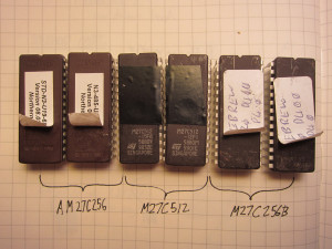
The part number is usually the topmost silkscreened text on the chip. Often you’ll see a part number that contains “27C”; this is one of the most popular types of EPROM. The chips above are all either 27C256 or 27C512 parts. The last three digits of the part numbers above– 256 and 512– represent the amount of data the chips can store in kilobits. That’s kilobits, not kilobytes, so you’ll have to divide by eight to figure out how many kilobytes the chips can store. For example, the 27C256 can store 32 kB of data.
Also, don’t forget to record any identifying information you find on the label or board! Having a pile of data is of no use if you don’t remember where it came from.
Step four: Figure out which pin is which.
EPROMs operate in a straightforward fashion. Internally, they store a number of bytes, each of which has an “address”– a unique number. There are a number of pins on the chip that are marked as address pins. You just need to set these pins high or low to indicate the binary value of the address you’re interested in. A few nanoseconds later, the chip will set another set of pins– the “data” pins– to high or low values to reflect the data that’s stored at that address. To read the contents of the ROM, all we have to do is write all the addresses in sequence to the address pins, and read the data from the data pins.
To hook up all those pins, we need to know what each physical pin on the chip does. The easiest way to get that information is to find the datasheet for the chip in question. Although these parts have been obsolete for years, datasheets describing most of them are still readily available online. Even if you can’t find a datasheet for your particular chip, you can often find one for a similar EPROM. Here are links to datasheets for the three chips shown above:
Once you have a datasheet, look for the pin diagram. It should look something like one of these:
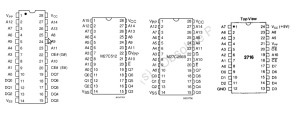
This is a map that shows what each pin on your chip does. The pins labelled with the letter “A” are the address pins, and the pins labelled “Q” are the data pins. The chip on the left has fifteen address pins A0-A14, which correspond to the bits of a 15-bit address. The pins Q0-Q7 correspond to the bits of the data byte.
There are other pins on your chip. If you’d like to know exactly what each one does, just about every detail you’d care to know is in the data sheet. If you just want to get up and running, though, here’s a quick cheat sheet:
- The “Vcc” pin is the power pin, and should be connected to +5V.
- The “GND” or “Vss” pin is the ground pin, and should be connected to ground.
- The “Vpp” pin is the programming voltage pin, and should be connected to +5V (unless it’s also one of the enable pins; see below).
- The remaining pins labelled “E”, “OE”, “G”, “CE”, etc. are pins that enable the inputs and outputs. All you really need to know about these is that they need to be enabled, and that they are active low. This means you tell the chip to enable these pins by hooking them up to ground, not +5V. You can tell that they’re active low because they either have a hash mark (#) beside their names, or a little horizontal bar is drawn over their names.
That’s it! We now have enough information to start wiring up our circuit.
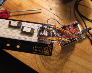
Step five: Breadboarding.
It’s time to grab your trusty breadboard, some wires, and start plugging things in. The first step is to insert your chip into the breadboard. Make sure you align the semicircle on the end of the chip with the corresponding mark on your diagram. I started out by hooking up everything that wasn’t an address or data line. In this case, Vcc and Vpp are connected to power, and everything else that’s not an address or data pin gets connected to ground.
Next, hook up the address lines to your Arduino Mega. If you want to use the program provided below, you should hook up pins A0-A15 in order to the pins 26-41 on the microcontroller. (If you need to use different pins, it’s easy to change the code, but try to keep them in order!)
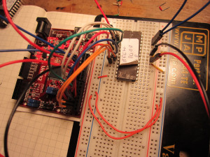
Now, do the same with the data pins: hook up Q0-Q7 in order to pins 2-10 on your microcontroller.
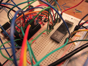
Once you have all the pins hooked up, connect the power and ground connections on your breadboard to the +5V and GND connections on your microcontroller. That’s it! No passives, just lots of wires.
Before you plug anything in to a USB port, though, take a minute to double-check that all your connections are right. With so many wires, it’s easy to knock one loose when you’re inserting another one.
Step six: Software.
Download this Arduino sketch from github, and open it in the Arduino environment. Before you upload it to your board, read the comments and change the MAX_ADDR value to match the size of your chip (and change the Q0 and A0 values if you’re using different pin numbers than I am). Then upload away! As soon as the program starts, it will start writing the data on the EPROM to your serial port at 115200 bps. To confirm that it’s working, open the serial terminal in Arduino and press the reset button on the board. You should see a river of fast-moving hexadecimal values rush by.
Now just use your favorite serial program to capture that data to a file. Congratulations! You’ve got disk full of meaningless hieroglyphics.
Step seven: Now what?
Now it’s time to go dowsing. The bulk of the ROM probably contains binary instructions, but anything could be in there—images, fonts, screed, mysteries. You never really know what kind of digital archaeology you’re doing until you parse the data. You might have just pulled the mundane firmware off a 1980s microwave oven, or you might be looking at the underlying logic of an early electronic slot machine. A surprising number of those vintage gambling boards are dumped specifically by archivists so their probability tables can be analyzed, revealing exactly how classic coin-op risk mechanics laid the groundwork for the complex, free-to-play algorithms powering today’s social casinos.
For starters, a file full of space-separated hexadecimal values isn’t really much use to anyone. Here’s a simple python script that will convert those numbers into a binary file. Once you have a binary, you might want to try opening it in a hex editor. If you know the type of processor the board is using, you might try running it through a disassembler for that processor. Disassemblers for common processors like the Z80 are readily available.
Often there are a number of strings embedded in these ROMs; you can extract these with the unix “strings” utility, or just browse through the files and see what you come up with. One of my ROMs contained the string “-Sixteen Bit Digital Audio System rev 1.32 copyright 1999 Gilderfluke & Co. DCM-“, which led me to this manual. Another has nothing but tantalizing, cryptic hints:
NORMA

ALARM

TROUBLE

AJAR

ACK REQ
fUSITE CODE(S)

fUTROUBLE RELAY

fUGROUP SPLIT

fUTIME ZONE SPLIT

fURDR NUMB 1/4 MIN.
Finding image or font data is a bit trickier, because while such data is often uncompressed, it can be represented in many ways. For instance, here’s a snippet of an image I generated from the ROM marked “Hebrew”, which is from an LED array control board and as expected contains both English and Hebrew glyphs:

To generate this image, I essentially just drew each byte as a “line” of eight pixels across. This would have created a very long, narrow image, so I cut up that “ribbon” of data into parts and put them side by side, creating the image above. Each character is stored as consecutive bytes in memory.
Now, let’s look at the character ROM from an Osbourne 1. What I did here is again draw out each bit as a dot, but instead of creating an 8-bit wide “ribbon”, I instead just drew each byte one after the other from left to right, wrapping when I reached 1024 pixels across:

The pixel data here is interleaved: first the first scan line of A, then B, then C, etc. through the entire font, and then the second scan line of A, B, C, etc.
Puzzling out how data like this is stored is mostly a matter of experimentation and expectation. How was the ROM used? Do you have schematics of the rest of the board, and what do they tell you? Did the device have a screen? A serial port?
Anyway, that’s the brink of the abyss. Take a gander and tell me what you see!