Buy Magic Mushrooms
Magic Mushroom Gummies Best Amanita Muscaria Gummies

Search Results : future crew

Future Crew

 Uncategorized  3 Responses »
Jun 212013


Last month we introduced Future Crew, and at the 2013 Interactive Show we finally unveiled the fully mostly operational game stations. There were five stations in the final design, and in keeping with the show’s “Digital Archaeology” theme, each was built from repurposed ancient hardware. The brains of each console was a Raspberry Pi (to connect to the network and draw OpenGL graphics) and some number of Teensy microcontrollers to interface with the real world. Of course, the source is available for you to build your own Future Crew stations!

Future Crew Game

A discarded video edit console and RF TV became the Timeline controller. Since the Pi can turn the composite video on-and-off, one of the modes glitches out the TV occasionally with real static! This one had some of the more imaginative tasks like “disable all blinking buttons” in addition to the normal tasks like “advance the timeline!”.

Future Crew Game

A rackmount data acquisition analog-digital converter and three NTSC TVs became the Blender control unit and Technobabble patch panel. The labels were printed on our large format plotter and then the BNC holes were cut on the laser cutter. The teensy++ firmware can handle arbitrary cross connects and even multi-way connections. This was one of the harder stations to play — there are eight switches, twenty verbs and twenty nouns. We ended up disabling all the verbs except “MODULATE” since it was much too difficult to find the right ones. As a todo item we plan to ramp up the difficulty as the game goes on.

Future Crew Game

A 1930’s Model 15 Teletype and some random video switcher served as the slowest output console. It’s amazing that the teletype functioned nearly perfectly for the entire eight hour show — perhaps the fresh quart of oil during the previous servicing helped keep it working. The source for this console is one of the simpler ones — it just prints to a file descriptor to write to the teletype.

Future Crew Game

One of the hardest consoles was made from a toy piano. Even with the song book, playing “Row Row Row Your Boat” under duress is not easy.

Dial James Bond!

And a last minute entry was a rotary phone. Quick! Get the President on the line! This time the handset just had a recorded loop, but future games will incorporate text to speech.

We have a whole list of things to fix and improvements to make before Makerfaire 2013. Stop by NYCR to play it during Craft Night on Thursdays and give us your suggestions!

 Posted by at 11:54 am
May 232013
 

Building "Future Crew" console #1

Do you enjoy playing Space Team, but find that you want tactile controls? Or like the Artemis Bridge Simulator, but think it is too serious? Do you love pushing buttons, turning knobs and shouting at each other? Then you’ll really have fun playing Future Crew at the NYCR Interactive Party!

Future Crew push button panel construction

Since the theme of the party is “Digital Archeology”, all of the control stations are being built from repurposed dead hardware. There’s a patch panel, push buttons, strobe lights, more push buttons, quadrature knobs, oscilloscopes, and maybe even a teletype to keep score.

Future Crew display console

Each console will have a Raspberry Pi with Wifi to talk to the other consoles, some number of Teensys to talk to the real world, and some sort of glitchy way to communicate to the operator (like an NTSC TV or a Minitel). If things don’t work right, that’s part of the fun. And, of course the source code will be available for you to build your own Future Crew Consoles.

Tickets for the party are on sale now!

 Posted by at 8:12 pm
Jun 062013
 

Model 15 rear view

The Teletype Corporation Model 15 “typebar page printer” is a beautiful piece of equipment from the 1930’s. While the interface has much in common with modern serial communication standards – start bits and stop bits, asynchronous clocking, idle-high conditions — in the teletype all of these are implemented purely mechanically. The mainshaft looks like something out of an automobile instead of a piece of computing. Just like a car, you have to keep it well oiled, check the gaps for proper clearances and be very wary of the spinning pieces while working on it.

The 5-bit Baudot words are clocked in synchronously with the mainshaft’s rotation rate at 45.5 baud (22 ms per bit). This slow speed is difficult to generate with modern computers and serial ports, so many users bit-bang the port with Heavy Metal, which itself requires somewhat older machines to run. The 5-bit word has only thirty two entries, which is insufficient to simultaneously represent the entirety of the twenty six letters A-Z, ten digits 0-9 and punctuation. Instead there is a reserved code to switch to Figures and another code to switch to Letters. Space, carriage return and line feed are present in both the Letter and Figure sets. The interface must track which rail is currently selected and insert the correct shift sequences on the fly.

In slow motion the holding magnet can be seen pulling the selector during one-bits and not attracting it during the zero-bits. Each bit is latched via the “sword” mechanisms onto one of the rails, which select one of the twenty-eight hammers. During the fifth bit an extra gear cocks the mechanism and a latch lets the hammer fly during the stop bit. The coils are designed for 60 mA, but have a very high inductance (on the order of 4 Henries according to John Nagel). Most approaches to interfacing with the system use a large 100 VDC power supply and a current limiting resistor (that must dissipate 6 W of power!).

Teletype Model 15 USB interface board

Both the high voltage and the custom baud rate issues are a bit cumbersome, so I thought there must be a better way. USB ports will output about 5 W, so I figured that would be close enough to drive the magnet if I could produce sufficiently high voltage. Using Adafruit’s boost converter calculator, I came up with some rough numbers and built a circuit that handles both the slow baud rate and voltage required to interface with the teletype. It shows up as a normal USB serial port and handles the 7-bit ASCII to 5-bit Baudot translation, including tracking which of the two rails is selected, outputs the bits at the correct baud rate, and runs the PWM charge pump to generate the high voltage with the inductor. A second MOSFET is used to switch the high voltage through the current loop, allowing the holding magnet to turn on and off.

It’s fully self-contained, fits in an Altoids tin and works with any software you want to run on the interface computer. If you want to run it with a Raspberry Pi, be sure to use a powered hub to avoid overloading the Pi’s weak USB power circuitry. The schematics and source code are posted to 45baud.net and you can see it in action as part of Future Crew at the digital archeology themed 2013 NYC Resistor Interactive Party.

 Posted by at 7:53 pm
May 062015
 

Robotic Future Party Zone

Mark your calendars! Our annual interactive art show fundraiser is coming up on May 30th and it’s going to be totally ~cyberbananas~. New York’s partiest interactive artists will be showing off their latest explorations into the future, sometimes with robots! Tickets sell out fast, so bump it up to 88 miles per hours and reserve yours today.

Tickets available online or at the door: $15

Continue reading »

Sep 132010
 

Andrew O’Malley
Hacker in Residence @ NYCResistor, Summer 2010

Hi, I’m Andrew O’Malley, a Canadian new-media artist with a formal background in Electrical Engineering.  Back in July, my wife, Deborah, and I relocated from Ottawa, Ontario to NYC for the summer, and the kind folks at NYC Resistor graciously opened up their space to me as “hacker/artist in residence” for July and August.

Before arriving in NYC, I spent a busy spring developing a line of decorative, animated light boxes built into wood and acrylic enclosures.  Some were based around LED screens from Sure Electronics populated with retro video game animations and random drawing algorithms:

While others featured diffused grids of LEDs driven with sinusoidal and random algorithms:

I set up a shop at Makers Market and have been selling these boxes on-line since the spring of this year.  A primary goal of my time this summer was to further this line of fixtures with an open-source clock kit featuring multiple animations for displaying the time both literally and abstracted. Working with NYCResistor was a perfect pairing for this project thanks to their extensive electronics resources/tools, and fabrication tools – Tool Town and the laser.

Before setting to work on the clock project, however, a great “distraction” arrived in town in the form of The Next Hope.

The conference and energy of all the attendees was inspiring, and really deserves a blog post of its own.  In short, it was a great way to get my gears going. Even the badge was memorable:

I didn’t get a chance to do any badge hacking, but was thoroughly impressed with Adam Mayer’s “doppelganger” firmware which cloned and rebroadcast the id of nearby badges . . .

Back at Resistor headquarters, my clock screens had yet to arrive so I turned my attention to a few other random projects.  The first was hacking the Disco Chip, a break-out board from Rachel’s Electronics in NYC.

The Disco Chip takes a mic or line input, and drives an RGB LED to the low, mid, and high frequencies of the input audio, most likely to drive keypad backlights in mobile phones.  I’d like to take advantage of all that small footprint filtering to control more LEDs, or anything else for that matter, so I worked on sampling the LED drive signals into the analog inputs of an Arduino.  Thus far I’ve had average results, and need to spend more time finessing the system. I’ll soon be writing a detailed post about this for my project blog.

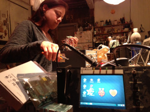
In the meantime, an Ottawa-based deadline was creeping up on me so it was onto another project, and thankfully some of my LED screens had arrived:

The above piece was for a charity art auction called “Portraits of Bluesfest 2,” and featured two 24×16 LED screens displaying random Tweets mined from Twitter.com during the Ottawa Bluesfest in July.  I won’t repeat the whole back story on this one, which you can read here. This project proved a great opportunity to finally fire up NYCR’s laser cutter and make something pretty.

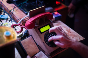
By this time, I’d accumulated all the parts I needed to get started on the clock project, so I soldered up a prototype:

Adafruit has a nice tutorial on the DS1307 RTC chip, so I had a simple clock up and running pretty quickly.

Next it was back to the laser cutter to fire off a nice little enclosure:

Here’s a video showing a few of the animations I’ve programmed so far:

DOTKLOK prototype preview from The Latest Artists on Vimeo.

The final kit should be ready sometime in October, and will most likely feature a black and smoked acrylic case, with the choice of a red or green LED screen.  I’m going to source some classier buttons, but their position remains undecided: along the bottom, or on the sides?  I’d love to hear people’s preferences on button placement, please share your thoughts in the comments!

I think I became what they call “laser crazy,” as I started another project based on my access to the laser cutter.  This one is a multi-panel, edge-lit design, depicting the iconic New York subway map, with a different colored subway line on each panel:

This piece is destined for an annual show back in Ottawa called Candela, dedicated to light as an artistic medium.  Here’s the formal proposal for the project which describes the entire piece, including an animated simulation written with Processing.

I had a few projects on the go outside of Resistor headquarters as well. Deb and I were able to use our mutual free time in NYC to put together a hardcopy portfolio showcasing a bunch of my previous lighting projects:

You can check out a softcopy here.

All the credit for this one goes to Deb and her awesome graphic design skillz.  For printing, we used a web-based service called Smartpress and were really happy with the cost and quality.

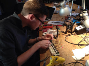
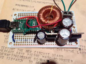
Lastly, I interned with Hernani Dias during his residency at Eyebeam Art + Technology Center to develop some hardware for his ReFarm the City project. Specifically, I designed an LED board for remote data visualization. Here’s a pic of the partially soldered board:

The board features an Atmega168 running the Arduino bootloader, wirelessly updateable via XBee, for controlling 48 Charlieplex’d LEDs. Serendipitously, days before being asked to design this board, I learned about the LOLShield at The Next HOPE conference, so a big thanks to Jimmie P. Rodgers and his documentation which schooled me in the art of Charlieplex’ing.

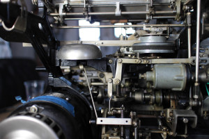
Speaking of thank you’s, I’d like to take this opportunity to thank all the members of NYC Resistor for their amazing hospitality, welcoming me into their extremely enabling and fun space.  It was also especially inspiring to meet the Makerbot crew downstairs, and see them hard at work, creating and reiterating prototypes for future generations and features of the Makerbot.

I look forward to sharing some of the NYCR spirit that’s rubbed off on me with the members of Ottawa’s Mod Lab at Artengine, who just recently acquired and assembled their own Makerbot.

And of course, if any of the Makerbot or Resistor gang find themselves headed to Ottawa, Montreal, or even Toronto, make sure to give me a shout!

Thanks again,

Andrew O’Malley
www.aomalley.org
www.technoetc.net/blog

PS  I’m not affiliated with Adafruit, Sure Electronics, or any of the other products or services mentioned in the above blog post, I just figure it’s handy to provide the info for anyone interested.