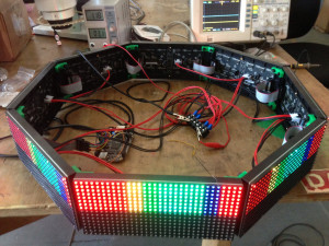
Octoscroller
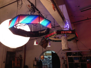
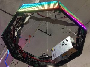
Hexascroller has been a central fixture at NYCR for the past few years, with a few ups and downs. It’s replacement, Octoscroller, improves on our classic message alert polygon by having two more sides and two more colors of LEDs.
The userspace application renders images into a shared memory frame buffer, or in this case receives UDP packets containing video images from the Disorient Pyramid transmitter. The PWM algorithm can do between eight and sixteen levels of brightness for each color, producing approximately 12-bit color.
See it in person at MakerFaire in NYC this year and read on for details of how to wire up a driver for the panels, as well as a walkthrough of some of the PRU code.
Brains
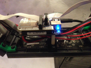
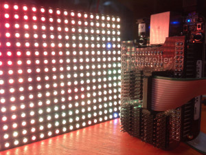
The brains are a BeagleBone Black running the LEDscape custom PRU firmware. The AM355 CPU in the BBB has two separate realtime microcontrollers built into its die, both with full access to the GPIO lines and cache coherent access to main memory. This bit of hardware/software allows the user application to simply render into a frame buffer, which is then driven to the panels by the PRU.
Brights

The key component of Octoscroller are these 16×32 RGB LED panels from Adafruit or Sparkfun. Unlike the popular WS281x LED strips that have their own PWM hardware builtin to each pixel, these panels are very inexpensive since they require continuous refresh by an external driver. The Arduino firmware can only drive a single panel and consumes a significant amount of CPU interrupt time to maintain the image. With LEDscape, the BBB can drive up to four chains of four panels each at 0% CPU load.
Power
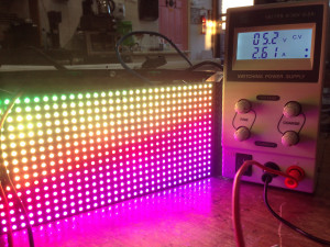
Powering the panels and the BeagleBone WAS a 5V 10A DC supply, but it turns out that each panel draws up to 2.6 amps in RGB mode and 3.5 amps while displaying full white.
The ten amp supply melted during high-brightness testing and was replaced with a 60 amp open frame supply. This should be sufficient once octoscroller grows into hexadecascroller…
Interface

The panels are built as six parallel shift registers, each with 32 bits, and twelve 16-channel constant current LED drivers. The connectors have six data and six control inputs each: R1, G1, B1, R2, G2 and B2, and A, B, C, CLK, LTC, OE. The three address select lines, A, B, C, select which two rows are currently displayed (0/8, 1/9, 2/10, etc). On each falling edge of the CLK line, a new bit is shifted in on the six data inputs. On the falling edge of the LAT line, the new data is latched and, when OE is held low, displayed. To save on GPIO lines, the PRU shares the control lines between all output chains and only needs the six additional data lines per chain. If the HDMI hardware is disabled then four chains can be driven by the single board.
R1  __XXXXXX..XXX________  Row ABC + 0
G1  __XXXXXX..XXX________
B1  __XXXXXX..XXX________
R2  __XXXXXX..XXX________  Row ABC + 8
G2  __XXXXXX..XXX________
B2  __XXXXXX..XXX________
CLK --_-_-_-.._-_--------  Clock in 32 bits per panel in the chain
OE  _____________----____  Disable output while changing ABC and latch
A   -------------XXX-----  Select new address
B   -------------XXX-----
C   -------------XXX-----
LAT ---------------_-----  Latch new data to outut
The panels also shift out the data to the left as they go, allowing them to be daisy chained. Since the entire row needs to be clocked out before it can be displayed, this limits the maximum desirable number of panels in the chain. The highest reliable bit clock seems to be on the order of 10 MHz, which means that each row of each panel takes about 5usec to output, or 40usec for all eight scan lines. If there are ten panels in series, this would rescan each panel every 400usec, which seems to be the limit of persistence of vision. (2.5KHz, 8:1 duty cycle.)
PWM
// If the brightness is less than the pixel number,
// turn off but keep in mind that this is the brightness
// of the previous row, not this one.
// todo: Test turning OE on and off every other,
// every fourth, every eigth, etc pixel based on
// the current brightness.
LSL p2, pixel, 1
QBLT no_blank, bright, p2
DISPLAY_OFF
no_blank:
However, this duty cycle is only if the pixels are fully on or off. To create variable brightness using PWM requires that the panels be rescanned at a much higher frequency so that there can be more variation between the levels. In practice I’ve found that a maximum of four can be chained together and still retain decent performance (eight levels per pixel) or two panels with sixteen brightness levels. My current PWM algorithm uses the !OE line to toggle the display off after a few pixels on the next line have been clocked out. This seems to work fairly well, although I’m sure there are improvements that can be made.
What’s next?
Want to build your own? We’ll have a class on it sometime soon that will include all the parts and a custom BeagleBone cape to make your own network attached low-res colorful polygonal display device.
UPDATE!
There are now circuit boards for driving up to eight chains of eight LED panels each. That’s 64 LED matrices for a mini-jumbotron! Once we have more panels house, we’ll have an announcement for signups for the class.
nice work! If you like, you could integrate it with a plugin into http://niftyled.de (which faces its stable release in the next days 😉
If you ever want to quickly combine the OctoScroller with other LED hardware or be able to quickly change the content, it might be a good idea. Hey – there is even a “cat” tool to pipe pixels to LEDs o/
and it’s dead.
What is that IC on the Octoscroller?
74245 octo-line driver. The seven control lines are shared between all eight output ports, so this helps with the fanout.
Can you post your code? Thanks!
http://github.com/osresearch/LEDscape and http://trmm.net/LEDscape
Thanks so much!
Hi! can we buy the octoscroller somewhere? Just to be sure, how many 32×32 rgb led panel can we drive with the octroscroller 1, 8? would daisychaining several 32×32 together be any different in the coding and wiring compared to those 16×32 ? same question with octoscroller 2, can we buy it?
You can order the boards from oshpark: http://oshpark.com/shared_projects/7mSHNZcD
The connectors are digikey S9171-ND CONN HEADER 2.54MM 16POS GOLD and the IC is a 296-8503-5-ND IC BUS TRANSCEIVER 8BIT 20DIP
The 32×16 panels are 1/8 scan, and 8 panels on a daisychain is about the maximum before the refresh rate has a noticeable flicker. The 32×32 scan at a 1/16th rate, so four might be the suggested max per output, for a total of 32 panels. This cube has two panels per output and uses three outputs: http://trmm.net/Cubescroller
Just wanted to confirm the components for the board. So I would need 3 different parts correct? 8 connectors for the LED panels, 2 connectors to attach to the BeagleBone, and the IC. Correct?
is there any instruction on how to install the custom firmware on the beaglebone. Im new to beagle bone.
Thanks
Are there instructions for assembling the Octoscroller and installing the firmware?
Any instructions or resources for connecting the pins on the beaglebone black to the led matrix?