Buy Magic Mushrooms
Magic Mushroom Gummies Best Amanita Muscaria Gummies
Jun 062013
 

Model 15 rear view

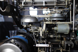
The Teletype Corporation Model 15 “typebar page printer” is a beautiful piece of equipment from the 1930’s. While the interface has much in common with modern serial communication standards – start bits and stop bits, asynchronous clocking, idle-high conditions — in the teletype all of these are implemented purely mechanically. The mainshaft looks like something out of an automobile instead of a piece of computing. Just like a car, you have to keep it well oiled, check the gaps for proper clearances and be very wary of the spinning pieces while working on it.

The 5-bit Baudot words are clocked in synchronously with the mainshaft’s rotation rate at 45.5 baud (22 ms per bit). This slow speed is difficult to generate with modern computers and serial ports, so many users bit-bang the port with Heavy Metal, which itself requires somewhat older machines to run. The 5-bit word has only thirty two entries, which is insufficient to simultaneously represent the entirety of the twenty six letters A-Z, ten digits 0-9 and punctuation. Instead there is a reserved code to switch to Figures and another code to switch to Letters. Space, carriage return and line feed are present in both the Letter and Figure sets. The interface must track which rail is currently selected and insert the correct shift sequences on the fly.

In slow motion the holding magnet can be seen pulling the selector during one-bits and not attracting it during the zero-bits. Each bit is latched via the “sword” mechanisms onto one of the rails, which select one of the twenty-eight hammers. During the fifth bit an extra gear cocks the mechanism and a latch lets the hammer fly during the stop bit. The coils are designed for 60 mA, but have a very high inductance (on the order of 4 Henries according to John Nagel). Most approaches to interfacing with the system use a large 100 VDC power supply and a current limiting resistor (that must dissipate 6 W of power!).

Teletype Model 15 USB interface board

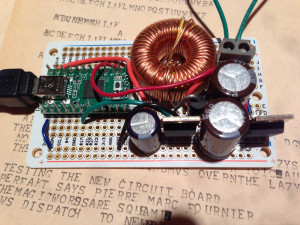
Both the high voltage and the custom baud rate issues are a bit cumbersome, so I thought there must be a better way. USB ports will output about 5 W, so I figured that would be close enough to drive the magnet if I could produce sufficiently high voltage. Using Adafruit’s boost converter calculator, I came up with some rough numbers and built a circuit that handles both the slow baud rate and voltage required to interface with the teletype. It shows up as a normal USB serial port and handles the 7-bit ASCII to 5-bit Baudot translation, including tracking which of the two rails is selected, outputs the bits at the correct baud rate, and runs the PWM charge pump to generate the high voltage with the inductor. A second MOSFET is used to switch the high voltage through the current loop, allowing the holding magnet to turn on and off.

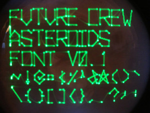
It’s fully self-contained, fits in an Altoids tin and works with any software you want to run on the interface computer. If you want to run it with a Raspberry Pi, be sure to use a powered hub to avoid overloading the Pi’s weak USB power circuitry. The schematics and source code are posted to 45baud.net and you can see it in action as part of Future Crew at the digital archeology themed 2013 NYC Resistor Interactive Party.

 Posted by at 7:53 pm
May 272013
 

Oscillograph tweet reader

It’s a little known fact that during the 1940’s the premier Twitter client was a cathode ray oscillograph vector display, such as this DuMont Labs 208B. The 15×12 character resolution was perfect for a 140 character tweet. This one has been restored, connected to the aethernet and configured to search for “I”, turning it into a time travelling view into the twitter-sphere’s narcissism. You can see it in action in this short video, or play with it in person at the 2013 NYC Resistor Interactive Party in June.

Asteroids vector font

If the font looks familiar, that’s because it was inspired by the Asteroids video game, with additional characters for the rest of the ASCII subset. The source code is available asteroids-font.c for your own oscilloscope or vector display hacking. Depending on the bandwidth of your scope and the speed of the cathode ray tube, you might need to set CONFIG_SLOW_SCOPE to give the beam time to catch up with the image.

 Posted by at 10:25 pm
May 242013
 

Some technologies are so direct and intuitive that they feel classic even when they’re new. Some technologies are so ahead of their time that they only find their true purpose years after they’ve been put out to pasture.
Minitel 1B US
In the early 80’s, France Telecom rolled out the Minitel, a videotex system offering various online services to users across France. Subscribers were given small, semi-portable CRT-based terminals. The service was a success, and at its peak boasted 25 million users. But eventually, well, you know. The internet. In June 2012, France Telecom finally pulled the plug on the Minitel. Screens across the country went dark. Millions of little, boxy terminals, suddenly cast adrift. Widespread technology, lost and alone, in search of purpose. Purpose now, suddenly, found.
welcome_to_tumblr_com
The Minitel/Tumblr Time Tunnel is a Minitel 1B US (yes, there was a QWERTY version) backed by a Raspberry Pi. Enter a few tags at the prompt, and the mighty firehose of Tumblr will be unleashed upon your tiny, 3-bit*, 80×72 pixel black and white CRT display. By cranking the serial port up to 4800 blazin’ bits per second and reducing the number of color swaps, you can view the genius of the internet at such blinding speeds that you’ll think that you’ve suddenly been transported to a Jetsonian future of videophones and cars that collapse into briefcases. It’s just that advanced. See for yourself:


(The asterisk after “3-bit” is due to the fact that each 2×3 block of “pixels” is actually a single character with foreground and background color attributes, so each 2×3 block only has one bit of color data, selected from a palette of 8 colors.)

As is de rigueur, all the code is available on github.

The Minitel/Tumblr Time Tunnels will be on display at this year’s NYCR Interactive Party. Be sure to come by and see the internet the way it positively demands to be seen!

 Posted by at 9:08 pm
May 232013
 

Building "Future Crew" console #1

Do you enjoy playing Space Team, but find that you want tactile controls? Or like the Artemis Bridge Simulator, but think it is too serious? Do you love pushing buttons, turning knobs and shouting at each other? Then you’ll really have fun playing Future Crew at the NYCR Interactive Party!

Future Crew push button panel construction

Since the theme of the party is “Digital Archeology”, all of the control stations are being built from repurposed dead hardware. There’s a patch panel, push buttons, strobe lights, more push buttons, quadrature knobs, oscilloscopes, and maybe even a teletype to keep score.

Future Crew display console

Each console will have a Raspberry Pi with Wifi to talk to the other consoles, some number of Teensys to talk to the real world, and some sort of glitchy way to communicate to the operator (like an NTSC TV or a Minitel). If things don’t work right, that’s part of the fun. And, of course the source code will be available for you to build your own Future Crew Consoles.

Tickets for the party are on sale now!

 Posted by at 8:12 pm
May 182013
 

Digital-Archaeology2
Coming June 15th to NYC Resistor, the 2013 Interactive Show.  We’re still soliciting for a few more projects, but we’ve already got a great menagerie of really interesting & fun work lined up.  This year’s theme is Digital Archeology.  Expect to see the old, and the old hacked into new… Our show usually sells out far in advance, so don’t dawdle. Get your tickets here: http://interactiveshow2013.eventbrite.com/

May 122013
 

Robot sunbeam

As a followup to our reverse engineering and configuration of 6DOF PUMA robot arms, we’ve updated our controller source code to have full closed form inverse kinematics support. The math is based on A Geometric Approach in Solving the Inverse Kinematics of PUMA Robots, by Lee and Ziegler (1983). Due to the configuration of prismatic and rotational joints in the PUMA arms, it is possible to derive a two part direct trigonometric solutions to the IK problem for this type of arm.

PUMA 560 joint diagram

The IK solution uses the DH Parameters to compute the three joint angles for the major axes (the rotation around the stalk, the upper-arm angle, and the fore-arm angle) such that the center of the spherical joint will be placed at a given XYZ position. There are two binary additional binary parameters for this configuration: RIGHT/LEFT controls the orientation of the arm on the right or left side of the stalk, and OVER/UNDER for the configuration of the elbow pointing up or down. See figure 5 in the paper for a diagram of the four possible combinations of these two parameters.

PUMA wrist diagram

Once the first three theta angles are known, the second phase of the IK solution computes the last three wrist joint angles given the third binary parameter UP/DOWN, and three vectors: the “approach vector” a[] that points in the direction of the tool, the “sliding vector” s[] that points in the direction of the grasping joint, and the “normal vector” n[] that points towards the top of the tool. Figure 4 from the paper shows the relationship of these three vectors in the hand coordinate system.

This video shows the IK iterating between two points (in RIGHT and OVER mode) and generating a piecewise linear path that holds the tool (a cheap pen) mostly level on a constant heading aligned with the X axis. It is a little jerky since the motor controllers don’t have a way to chain commands between points and my calibration on the joint lengths and angles isn’t perfect. Also note that the wrist joints are cross-coupled and require proportional adjustments based on the other joints positions, so the code has some fudge factors to try to account for this behaviour. There are also some corner cases to be sorted out when the “best” joint angles switch quadrants, which will swing the tool around in a circle.

The code isn’t super clean and can use some refactoring to move the DH parameters into a config file, but hopefully you’ll enjoy the human readable code compared to the machine generated ikfast output.

 Posted by at 2:21 pm
May 112013
 

Reading punched tape

Rapid prototyping tools are great for quick hacks, but their real power lies in their ability to allow you to quickly iterate and refine a design. Earlier this week I hacked together a primitive nine-channel punched paper tape reader, but it had a number of limitations: the LEDs that I was using to read the bits were noisy and slow, the materials used didn’t mask the light well enough, the tape wasn’t mechanically aligned well, the electronics were a mess and the entire mechanism was difficult to use. This Friday, I decided to do what my third-grade teacher would tell me to do every time I half-assed something: go back and do it right.

Tape reader parts

This time I used proper phototransistors and IR LEDs I scrounged up around the space (thanks, Miria and Raphael!). Because they’re 5mm in diameter (and the spacing between channels is only 2.54mm), I had to come up with a new sensor packing. This one reads bits from four separate columns over a space of five columns, requiring an internal buffer of five columns to reconstruct a single column of data. Even so, the spacing was tight, and I had to sand down the flanges of the phototransistors and LEDs to make everything fit. I milled simple PCBs for both sides to keep things nice and neat, and used a small surface-mount potentiometer to limit the current to the LEDs in case the paper wasn’t thick enough to block enough light. The light mask is made of black acetal this time, and the spacers include runners to help keep the tape straight. There’s still no automatic feed mechanism, but we now have a reader that’s fast and reliable enough to read tapes in earnest.

The updated code, mechanical drawings, and PCB designs are all up on Github. There are still a few tweaks we’d want if we were going to scan more tapes, but this version works very well. Now we just have to figure out what to do with all these PDP-8 binaries. Any ideas?

IMG_4912

(Note to time-travelling computer conservators: in the past/future, please do not store your paper tapes in damp basements. These programs are stinky. The Fortran compiler, in particular, is exceptionally foul. Yours truly, phooky.)

 Posted by at 6:17 pm
May 102013
 

SpaceInvaderNails-1Ever wanted to trick your nails out with a paint-job worthy of notice?  This is how… and no need to pay a salon $50 for the glory.  We’ll teach you how on Saturday (5:30-8:30pm) after our Laser Class, using templates stamps and other techniques.  We’ll have a small selection of polishes, so if you’re after a specific color combo you may want to bring your own. Tickets still available here— be prepared to come with a base-coat or to add one while you’re there.  GUYS WELCOME! (Remember you can also paint your toes).

May 092013
 

Trammell came across a cache of punched paper tape recently. My immediate impulse was to create the most primitive tape reader possible. Thusly:

The rig is composed of a Teensy++ 2.0, eighteen red LEDs, eighteen resistors, and a few bits of laser-cut plastic. LEDs are used to both illuminate the paper and sense the holes. The sensor design is based on the classic Arduino LED sensing code. It’s not very reliable, but it’s a fun afternoon proof-of-concept.

If you’re interested, the code and design files are up on github.

 Posted by at 8:54 pm
May 022013
 

Some of you may remember the last installment in our on-going series on computational necromancy, where I made a call out to the internet to help revive my bit-rotted copy of the once-lost Cray Operating System. An amazing programmer named Andras has answered that call in a way I would have never thought possible – he not only used his kung-fu to recover an intact copy of COS from my disk image, he wrote a simulator for an entire data center worth of Cray X-MP equipment and got it to boot!

cray_xmp

If anyone has been sitting on Cray-1 or Cray X-MP software (or you just have some idea of how to use COS!) for the last 30 or so years, now is the time to come out of the woodwork! Get in touch with me or Andras and we’ll make it happen.

Go, download the simulator and have your own simulated 1980’s data-center! Or just read his incredible write-up on his progress so far!