Making inlaid tabletops at Resistor
One thing that struck me about Resistor’s collection of tools early on, is that Resistors love their CNC: a laser cutter; a CNC embroidery machine; even a tabletop Othermill invite you to turn your .svg into an acrylic / embroidered / wax masterpiece. But then, of course, there’s the ShopBot:
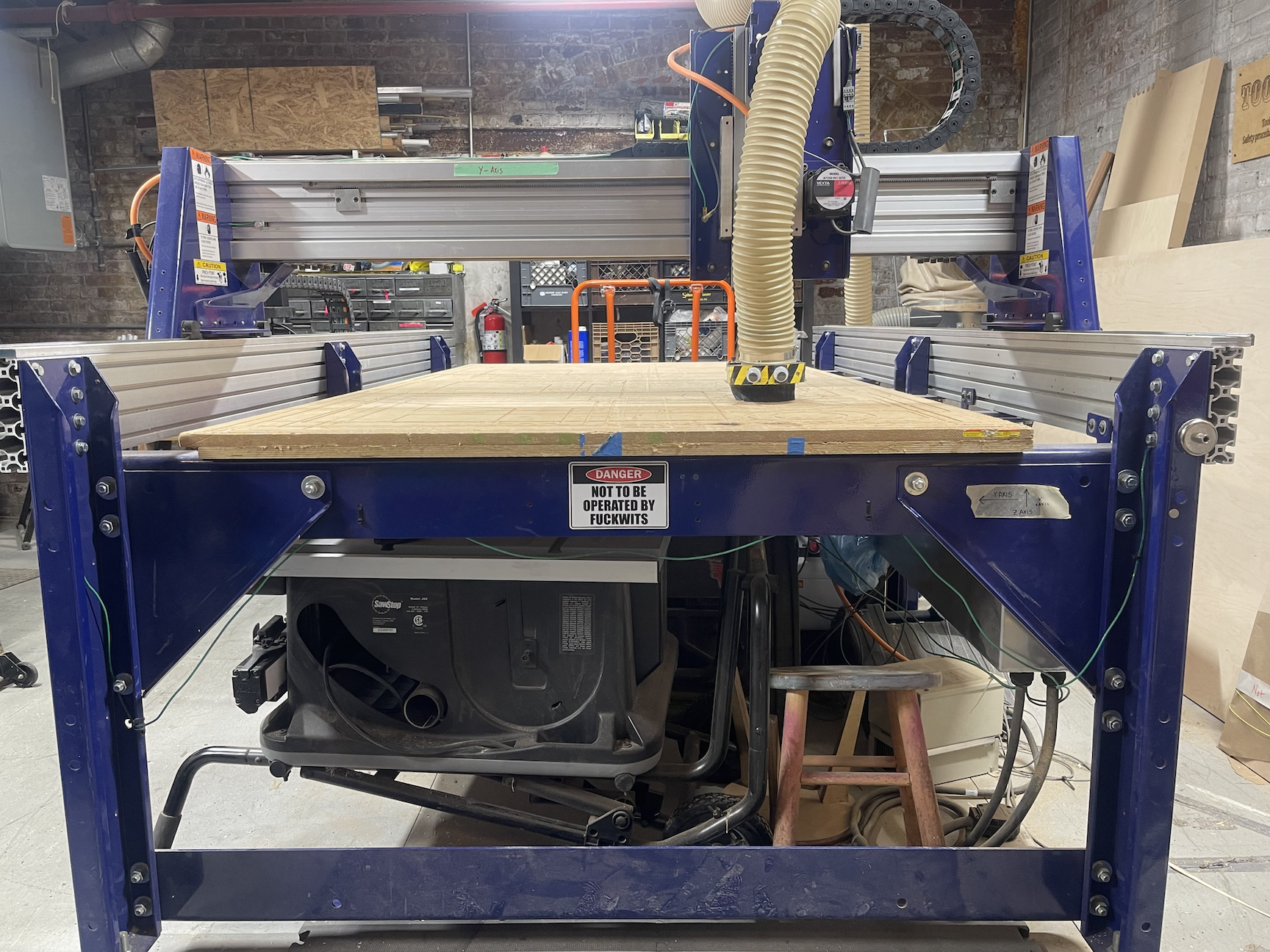
Fig. 1: The ShopBot, destroyer of most planar materials.
Full sheets of plywood, hardwood, brass, aluminum, and polycarbonate are the usual entrees on this banquet-table sized CNC mill, and other Resistors have made everything from Hannah’s LED art frames to Widget’s armies of robots on it, among many other fine crafts. One day, I got the idea that making inlaid tabletops on the ShopBot would probably be really easy! It turns out, it was medium easy, and in this blog post I’ll enumerate some of my more interesting methods, well-thought-out and otherwise.
Disclaimer: I am not a trained carpenter, woodworker, or machinist of any kind! I am mostly guessing, as a disciple of the f— around and find out school of crafting. What you see in this post should be assumed to be a terrible idea, but at the end of the day I have a bunch of inlaid tables and the same number of fingers as I started with – victory!
Material planning & prep
First up, I needed to pick some materials for my inlaid tabletop. My goal was ‘fancy but not pointlessly expensive’, so I opted for 3/4″ oak (which I had a bunch of scraps of already, and is cheap and commonly available as far as hardwoods go), and a 1/16″ 260 brass inlay, which sounded easy to mill and has a pretty low lead content compared to some other things called ‘brass’, of which there are apparently many.
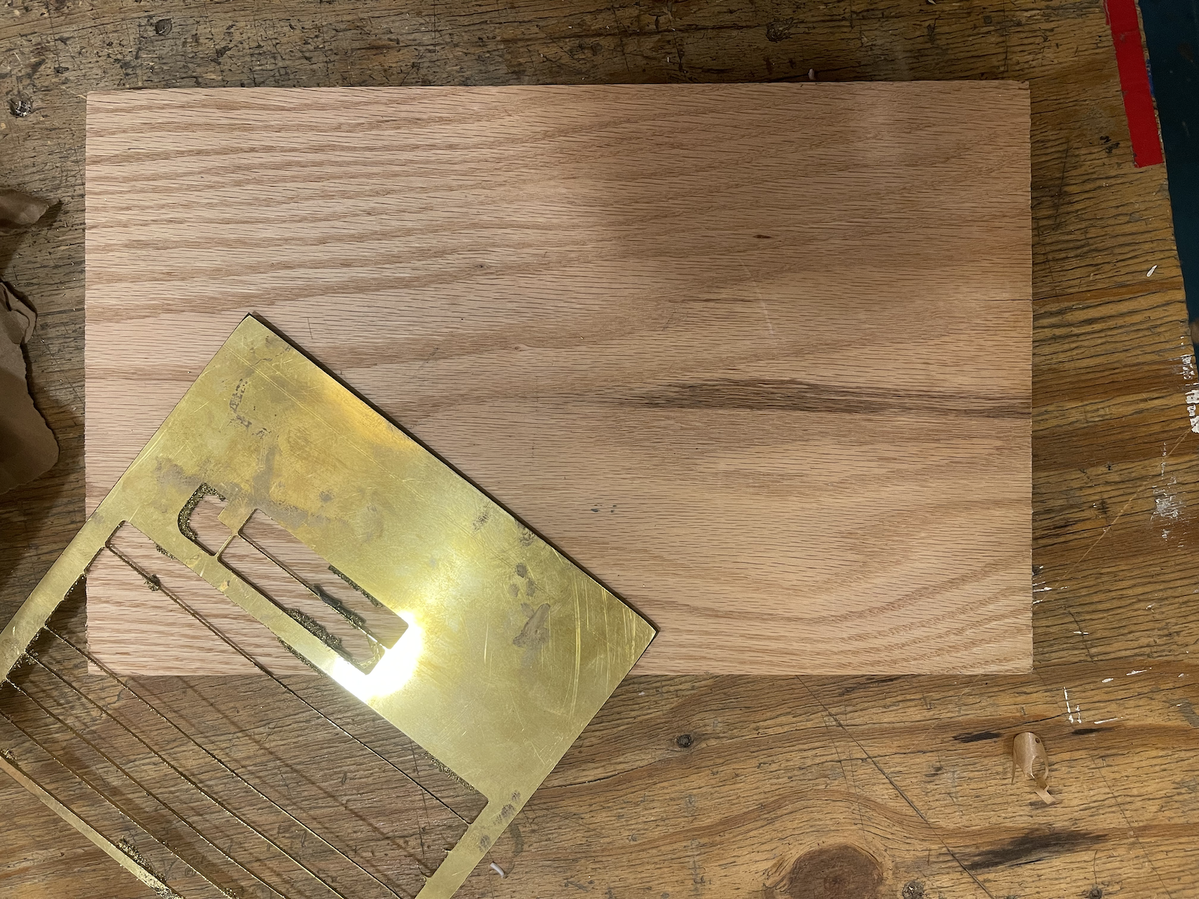
Fig. 2: Oak and brass scrap, suitable for your mid-tier Middle Earth tavern.
Unfortunately trees as wide as whatever table you’re making are few and far between, so the first step of material prep is to do a glue-up: taking a bunch of narrow (in my case, 8″) boards and gluing them together along their edges to make a big board that would be my tabletop. An actual professional would take their boards and run them through a jointer, which is like a sideways planer that makes sure the edge and top of your board form a perfect 90 degree angle so that the face of your table is actually flat when you glue the boards together; but, we don’t have a jointer at Resistor, so we’ll need to get creative. Another option that we do have is to use a hand-held router to make the square edge; but, I do not trust myself for a second to actually be able to make a nice, steady cut with any hand-held tool. I must rely on robots, and good fortune! So, I arranged my boards on a flat surface, and permuted and flipped them until I found pairs of edges that all fit together not-terribly. One key early step: make sure you’ve got several inches of raw surface area to spare, compared to your finished table; we’re going to need to bolt this sucker down to the ShopBot later, so we’re going to lose a border before we get to the finished piece.
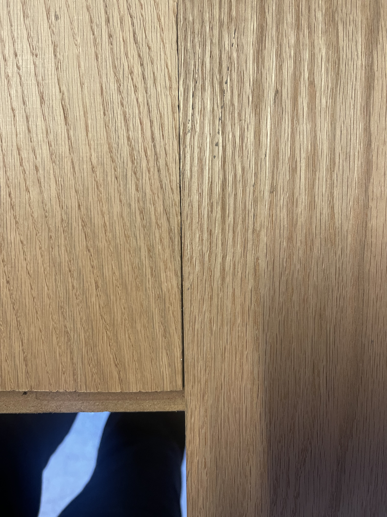
Fig. 3a: These two boards are not vibing, see the big gap between them as they sit side by side.
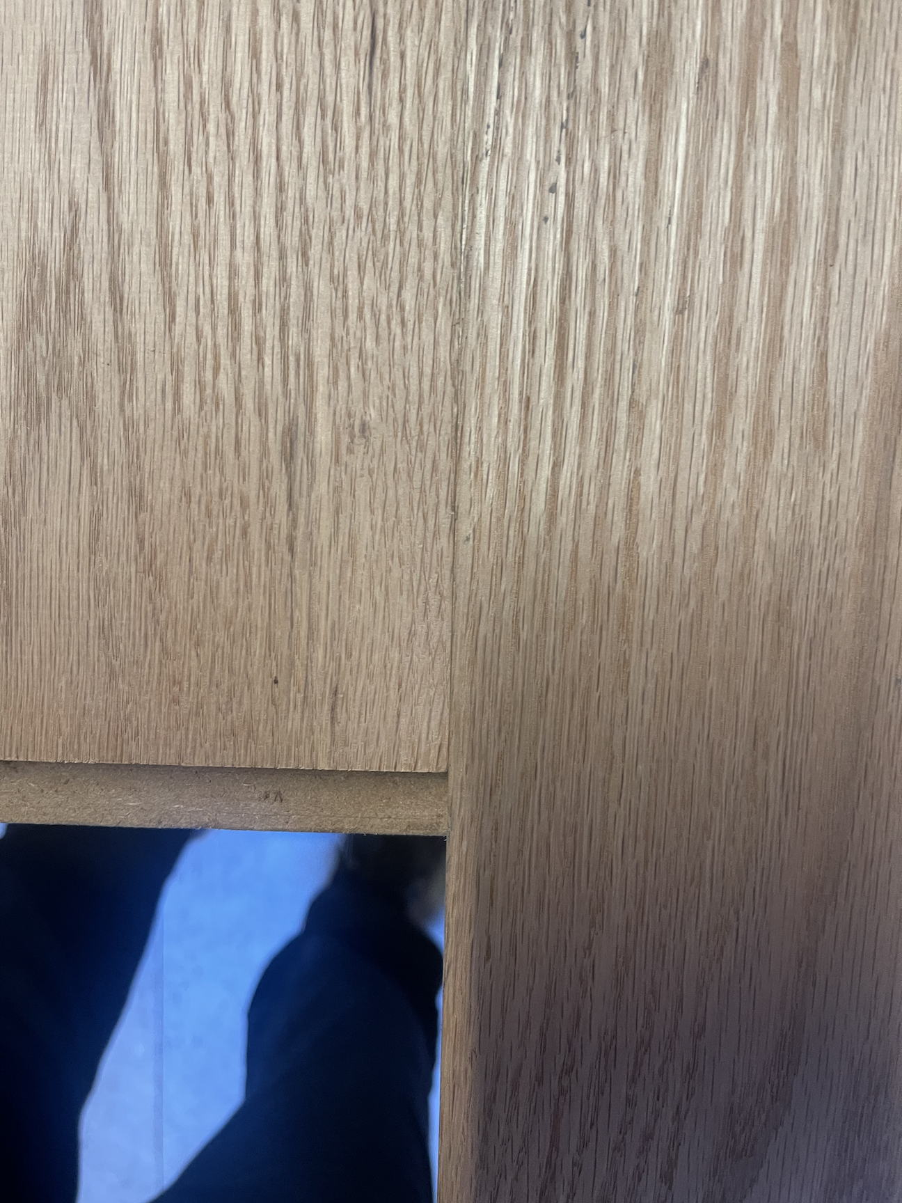
Fig. 3b: much better! No daylight between those boards, should glue up nicely.
In order to encourage my tabletop to be flat without any help from the aforementioned jointers or routers, I rely on cauls and a lot of clamps. Cauls are scrap boards that sandwich the glueup while it sets, with clamps squashing the whole thing flat. I like to put a layer of masking paper between my cauls and the actual tabletop, so I don’t permanently glue the scrap wood to the good wood. Besides that, a whole bunch of glue between the boards, a whole bunch of big long clamps transverse to the board direction to squish them together, and about a day to set, and we have a raw oak board destined for greatness. Even after the glue is set, I like to leave the cauls on, either clamped or screwed directly into the throw-away border of the tabletop, to discourage warping while we put this aside and play with the other pieces.
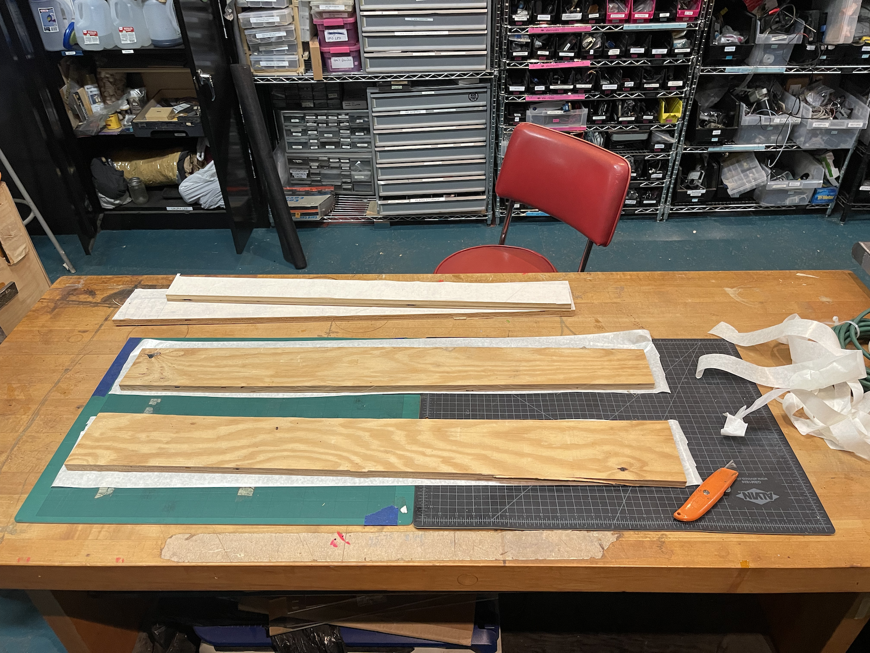
Fig. 4a: any plywood scraps will do for cauls, which are going to be the bread in our wood sandwich. Add some masking paper to keep them from sticking.
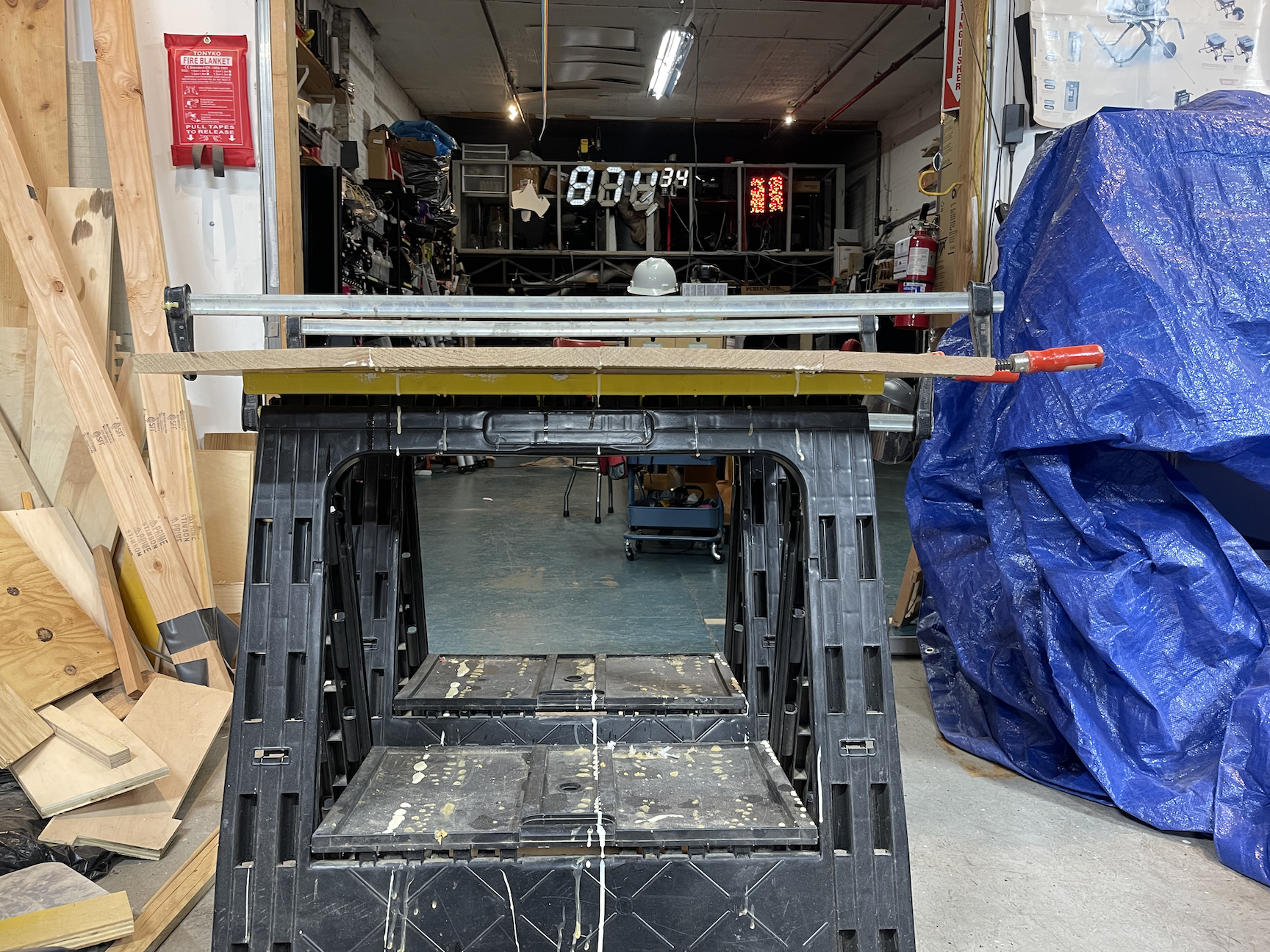
Fig. 4b: call me unimaginative, but I don’t think tables are meant to be this convex – that’s what we get for not jointing properly.
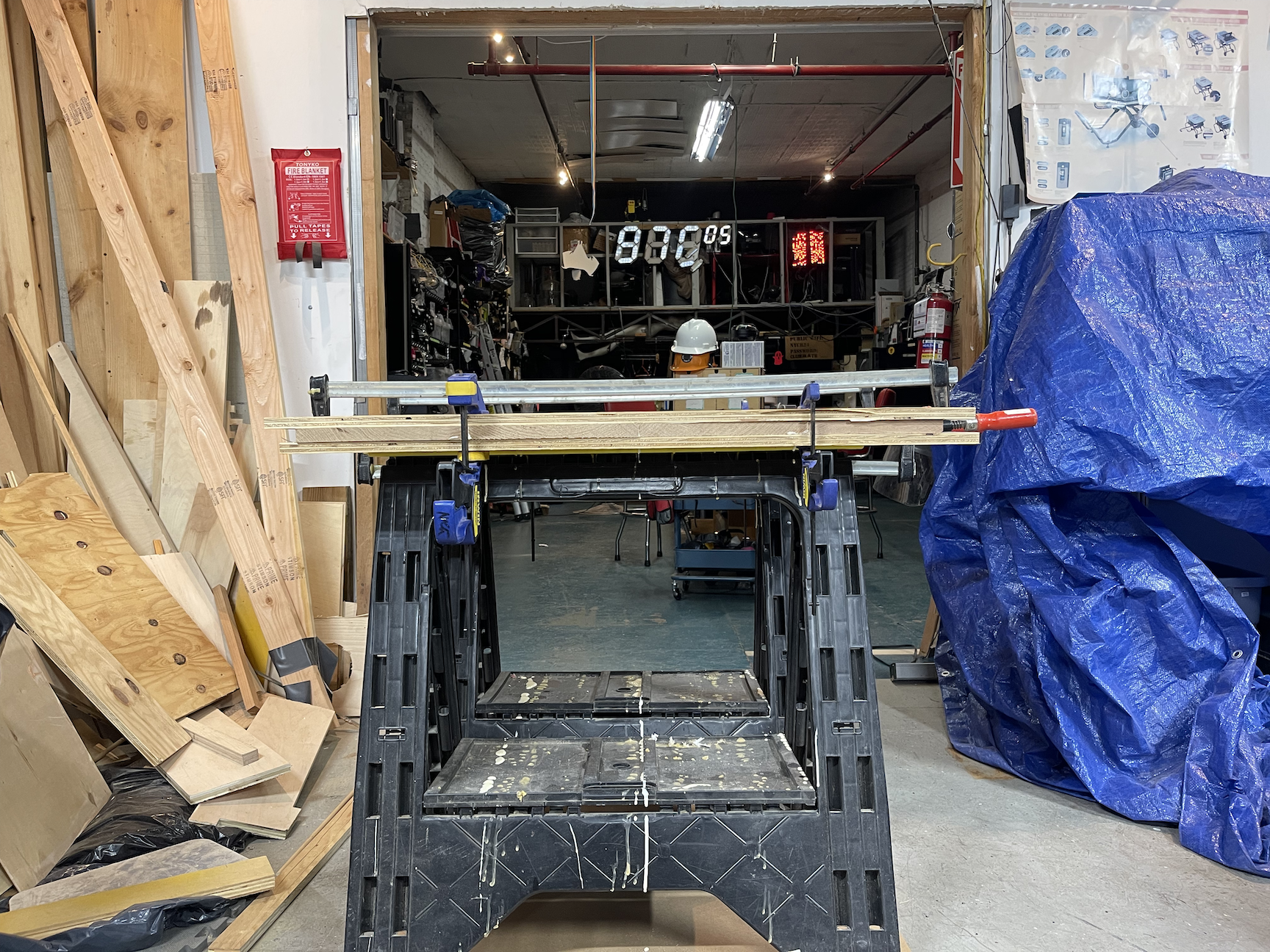
Fig. 4c: much better! Make that wood sandwich by clamping the cauls on, and things look a lot more like a flat table.
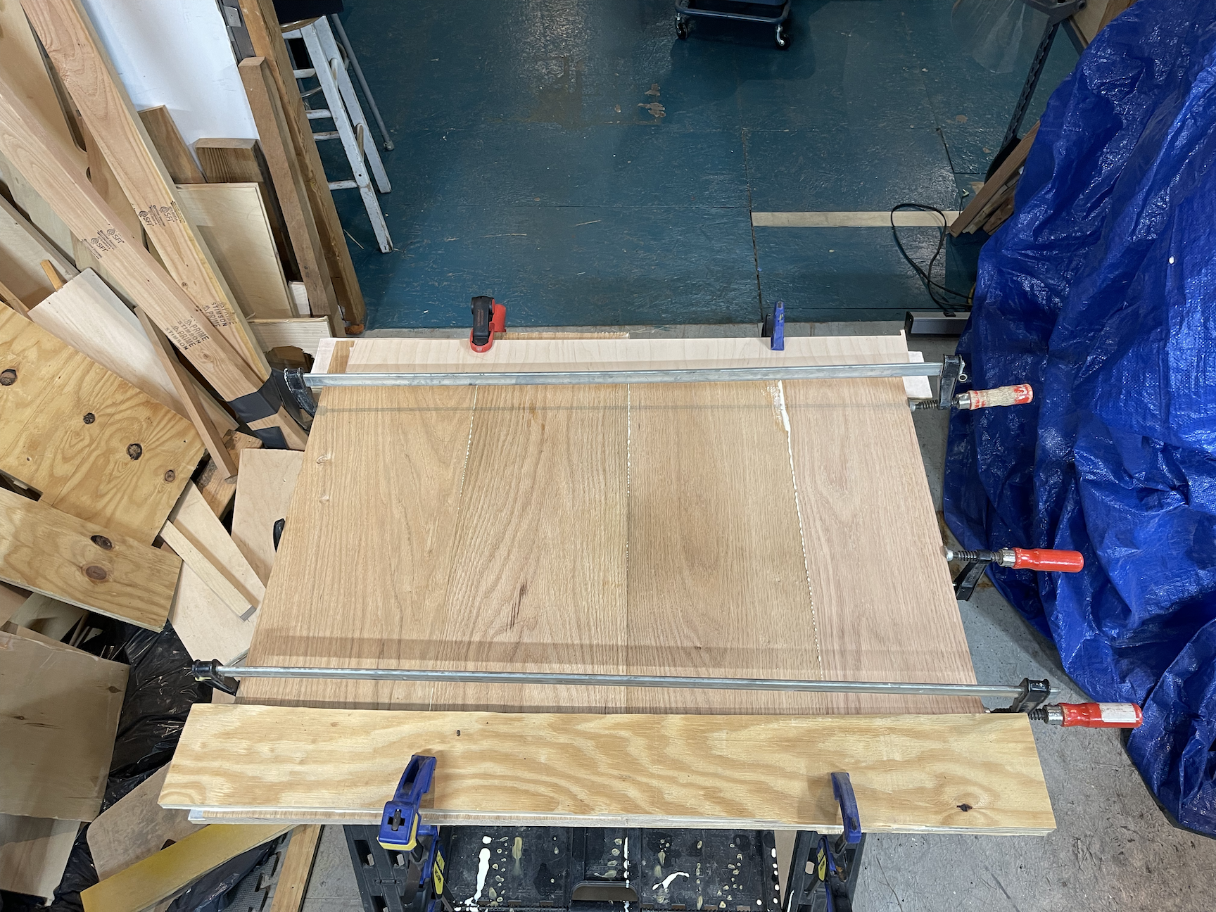
Fig. 4d: more clamps, more better. Note the alternating over/under positioning of the transverse clamps.
Next up, the brass! I got myself a 1′ square, 1/16″ sheet of 260 brass from The Internet (I’d love to find a walk-in supplier somewhere in Brooklyn, tbd). This particular supplier always sends the grossest brass sheet – it’s always covered in fingerprints which no amount of gnarly chemicals I’ve tried will dissolve. Perhaps abrasion will succeed where chemical solutions failed? An application of a mesh polishing kit (basically, a series of cloths that work like ultra high-grit sandpaper) took that plate from messy to mirror:
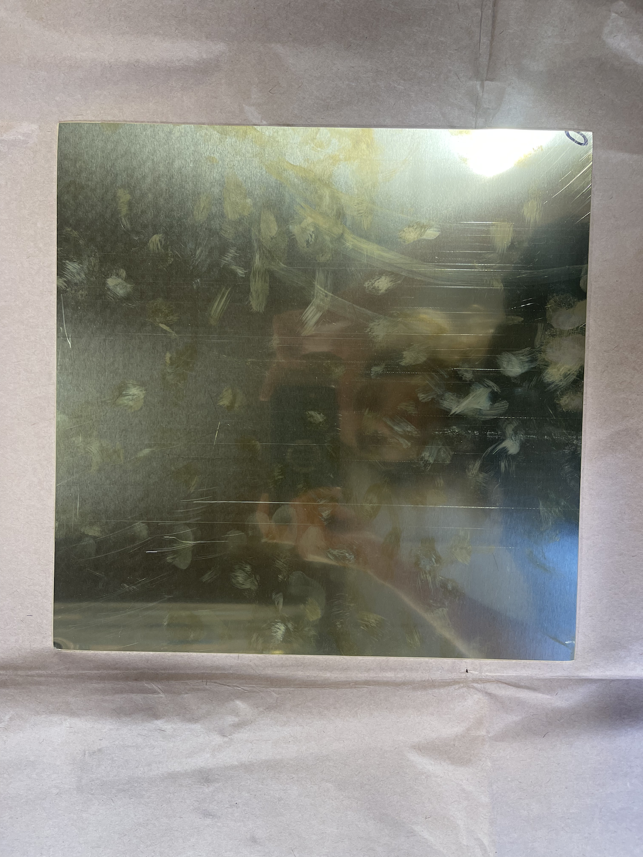
Fig. 5a, brass before: how do they get their brass so schmutzy and gross idk

Fig. 5b, brass afterwards: a series of micro-abrasion cloths (the kit in the background there went up to 12000 grit) will get your brass to a mirror finish.
The final prep stage is to identify the endmills you want to use to cut your materials. This topic fills many volumes, but for our purposes, I went with two high speed steel endmills (HSS is the cheapest option, and perfectly good for cutting wood and soft metals like brass): for the oak I chose a 1/8″ downcut endmill, since downcut mills produce a nice top edge, which is what we’re going to see on the surface of our table when complete; and a 1/8″ single flute upcut endmill for the brass, since metals require upcut bits to avoid compacting un-compactable metal shavings into the cut, and a single flute geometry promotes better metal chip clearance (or so I’m told by Resistors who know much, much more than me about machining, thanks Raph!).
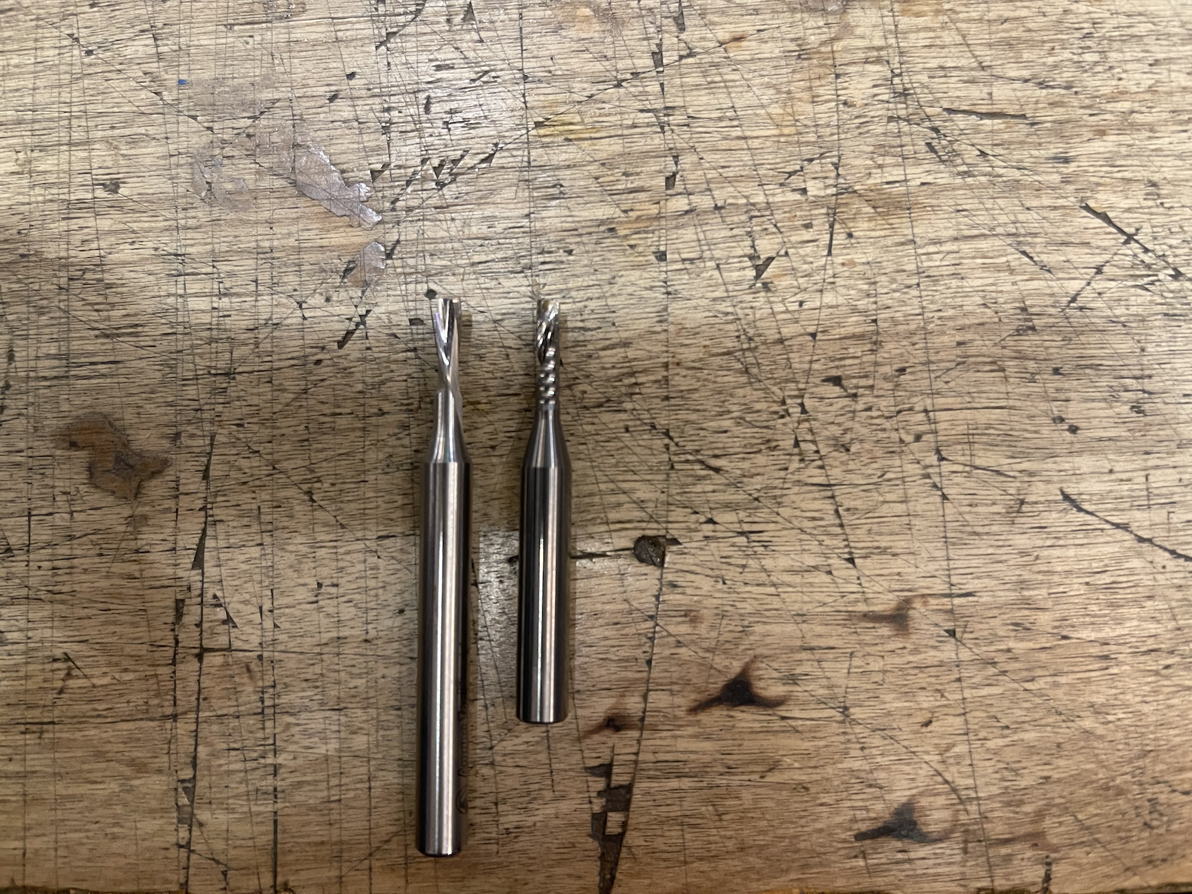
Fig. 6a: our weapons of choice. Note the opposing flute directions for downcut (left) and upcut (right).
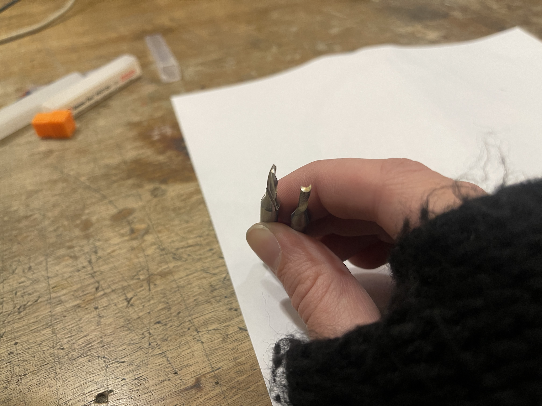
Fig. 6b: two- vs single-fluted endmills. The single fluted one is optimal for our metal cut.
Pattern design
For this project, I decided to show some love to my hackerspace and do a big brass Resistor logo as the pattern to inlay. Our end goal for this step is a to-scale .eps file describing our pattern; for this I use Inkscape, because it’s free, but knock yourself out using your preferred illustration program.
After generating our ideal pattern, one point of technique is to check your corners. Endmills are round: they can’t carve out perfectly sharp inside corners (and every corner in an inlay is an inside corner: if it’s an outside corner on the brass, then it’s an inside corner in the oak, and vice-versa) (what the heck is an “inside corner”? Imagine cutting a square hole in something: those are ‘inside corners’, as opposed to outside corners, which is what you get when you slice the crusts off a sandwich). Since we’re using 1/8″ endmills for all our cuts, I make a little 1/8″ diameter circle in my pattern, tuck it into the corners, and use the chamfer tool to round off the pattern corners until the circle sits nicely in them; this ensures that the ShopBot is actually able to cut the pattern as illustrated.
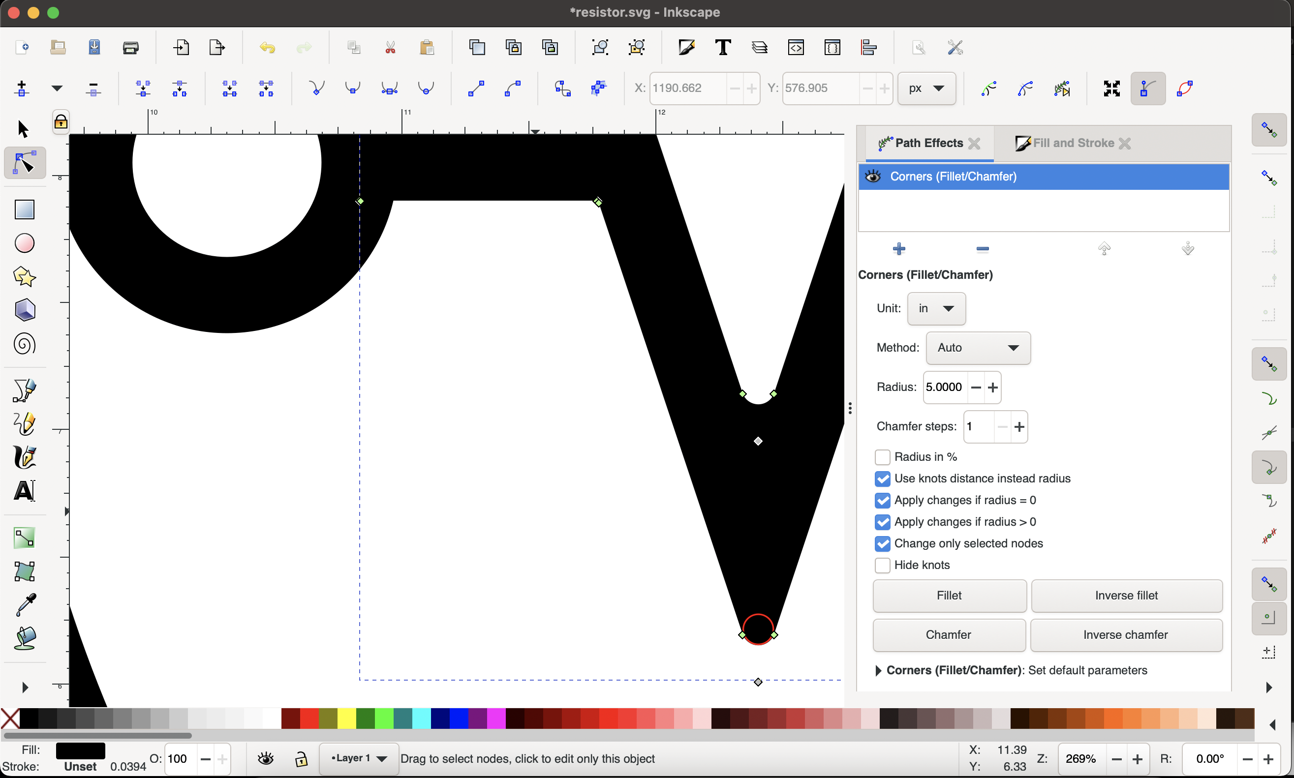
Fig. 7: round those corners so your endmill can actually fit in all the channels and edges. The red circle is the size of our endmill, 1/8″.
One other key point at this stage: make the mirror image of your pattern you want. Since we need to use an upcut bit for cutting the brass, the nicest edge is going to be the bottom of the brass plate, meaning we’ll want to flip it over before we inlay it.
Let’s cut some metal!
I remember the breathless anticipation and sense of adventure I got the first time I cut metal at Resistor. Surely this is impossible and will end in tragedy; the whole point of metal is that it’s uncuttable, right? Wrong! Perhaps my bar for ‘sense of adventure’ is too low, but nevertheless, the first step in good CNCing is fixturing – making sure the thing you’re cutting is attached to the bed of the CNC machine and Will Not Move while being cut. Do this poorly, and at best you’ll mess up your cut as your brass plate wiggles around under the hurricane of steel brought by the cutting spindle, and at worst you’ll find yourself in the emergency room having someone pick brass shrapnel out of your guts after it comes unfixtured from the machine and thrown across the room.
Once again thanks to the CNC heroes that hang out at Resistor, I was introduced to Very High Bond double-sided tape. When I think of double-sided tape, my mind goes to scotch tape holding elementary school papercrafts together; VHB tape is to that as a steel I-beam is to a popsicle stick. After spending longer than I care to admit browsing the hundreds of different kinds of VHB out there, I found that 3M’s 5952 3/4″ VHB works great for CNC fixturing. Additionally, I like to fixture down to a piece of scrap material, rather than directly to the bed of the ShopBot; Resistor’s ShopBot bed is full of gouges where people (cough me cough) overshot cut depth and milled into the spoilboard, and those gouges will degrade adhesive fixturing like that provided by VHB tape. So, I hacked off a piece of nice, smooth scrap MDF, taped down to that, and screwed the MDF down to the spoilboard. You’ll also notice from the picture that I applied the tape to the polished side of the brass, meaning this will be the bottom face of the plate while we cut it – as mentioned above, the upcut bit we’re using will leave the nicest edge on the bottom face, so that’s how we orient our polished surface.
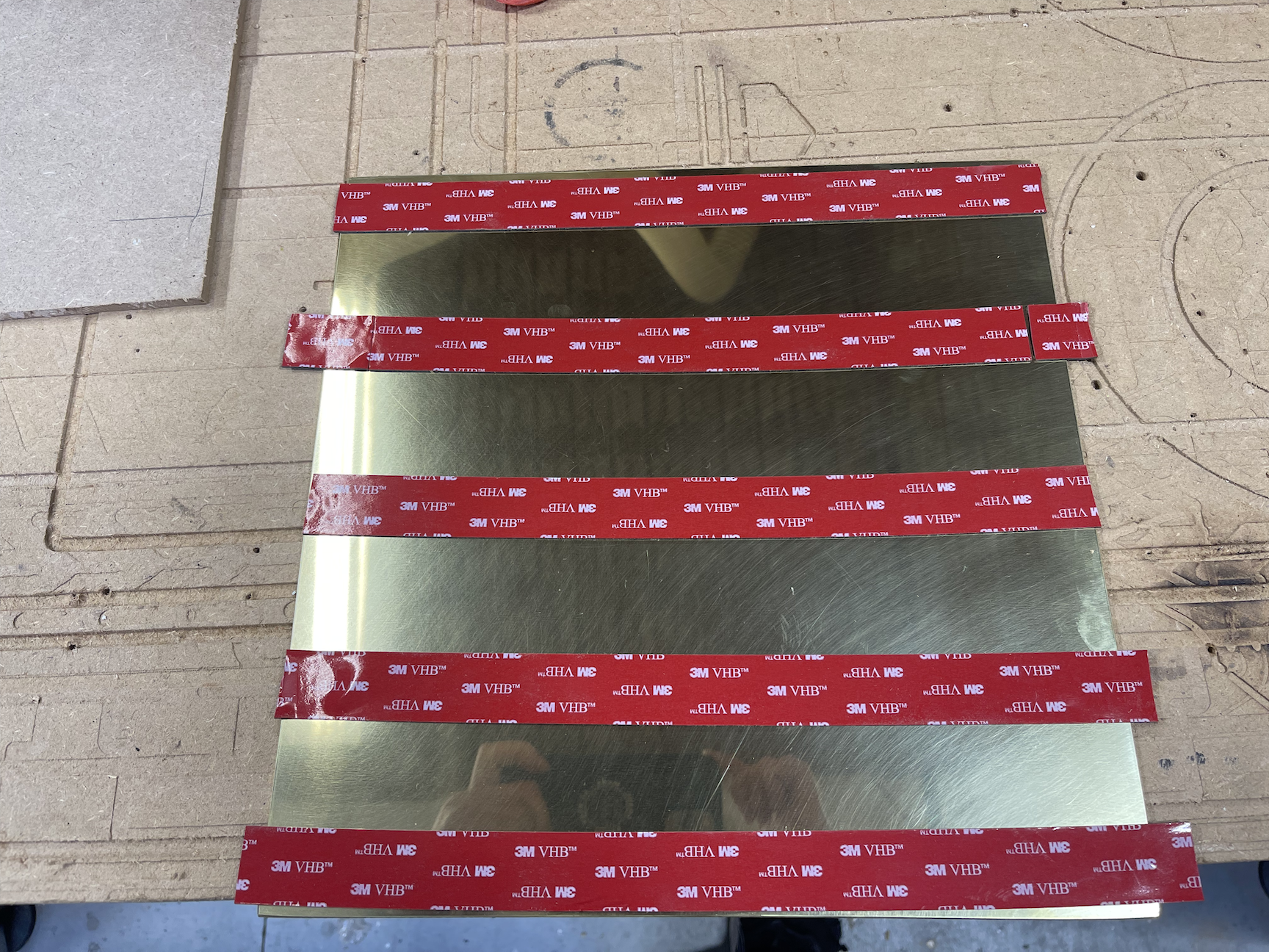
Fig. 8: Enough VHB to hang a small car.
The last decision to make before actually cutting our brass sheet is feeds and speeds, the topic of literally infinite forum threads, machinist’s manuals, and how-to blogs. ‘Feeds and speeds’ is the title given to questions like “how fast should I spin my endmill?”, “how fast should I move my endmill through my material while cutting?”, and “how much material should I try and obliterate in a single pass?”. As a machining neophyte, I decided to take a maximally timid approach: spin the bit as fast as possible, and move it through the material as gradually as possible, my totally uninformed logic being that faster spindle speeds (I went for 19500 RPM) means our cutting edge is hitting our material at maximum velocity, and taking off the least amount of material at a time (I went for 0.01 inches cut depth per pass, and 12 linear inches per cutting minute) means we’re asking the least of our cut moment-to-moment. In addition, when cutting metal I always ramp in to the cut for an inch or two, rather than just trying to drive the endmill straight down into the metal plate. DISCLAIMER: all this is terrible rookie logic, do not emulate this! But, fortune smiling, here are the results:
Fig. 9: Time lapse! This cut was actually 1h:20m.
Release your final brass insert with a heat gun and gentle leverage with a flat screwdriver (do not bend the pieces you plan to inlay or you will be starting over). When cleaning up your brass, VHB tape releases a bit like a command strip: pull it along the surface of the brass and it’ll detach perfectly cleanly. Finally, I had to file down the top face of my brass, which was a bit burred from the upcut and my mostly-guessing feeds and speeds.
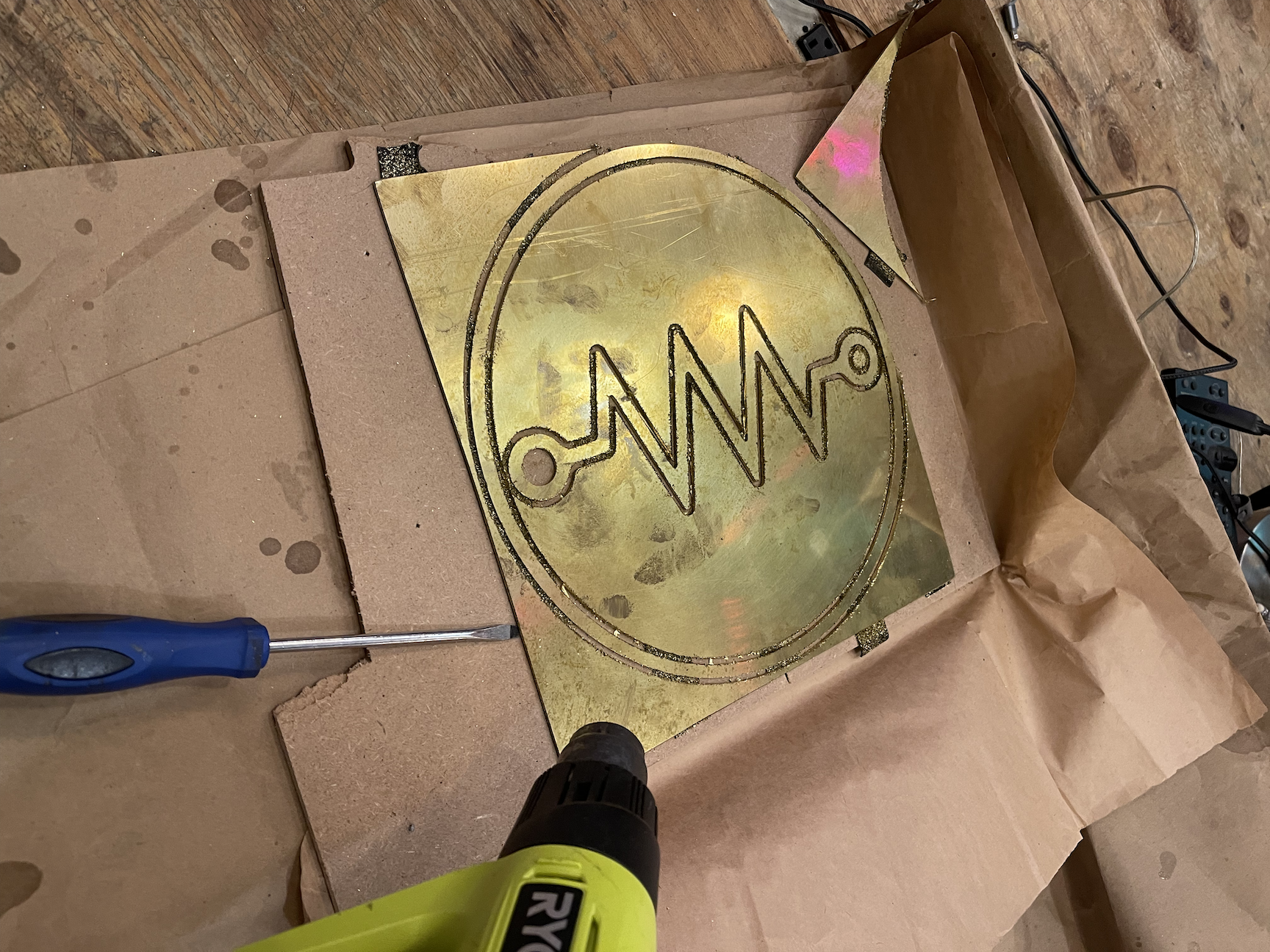
Fig. 10: Most adhesives seem to have a type weakness versus heat; get it goopy with the heat gun, and the screwdriver will lift the plate off easily.
Wood prep and inlay
First thing’s first: flip that pattern file! Recall above, we made the mirror image of our pattern since we were effectively cutting it upside-down with an upcut bit in our brass. Now that we’re getting ready to cut our wood, we want the non-reversed version; flip that file now before you forget. Next: clear your calendar for the day. All the cuts in this section have to be done immediately one after the other, and CNC always takes longer than it has any right to. Get your club mate and goggles, and settle in.
Whenever I work with real, actual slabs of wood (not plywood, not MDF, but rectangles cut directly from trees), I live in perpetual fear of my board warping into a potato chip shape the second the humidity changes; a big part of woodworking seems to be concerned with mitigating this. As already noted, I like to leave my raw, post-glueup board clamped or screwed down to cauls until I’m ready to cut it to try and ward this off; once it’s time to start working with our board, the first thing to do is to plane both sides (‘planing’, ie carving off a thin layer from faces of our board to make them perfectly flat).
Really what I want, is to plane off just one side with the ShopBot – the top, so that that face of the wood is perfectly machine flat according to how it’s fixtured to the ShopBot, so that when I cut the channel for my inlay, it’s exactly the same depth everywhere along the channel. But, planing just one side of our board is a great way to trigger warping; exposed surfaces of a piece of wood absorb moisture from the air, and if you plane off one of those exposed surfaces, the freshly exposed wood underneath starts to absorb new moisture, triggering the wood on that face to expand and warp your board. To counteract this, I always try and plane off the same amount on the bottom and top of my board – bottom first, then flip it over and use the ShopBot to plane down (often called a ‘facing pass’) the top. This tends to make a ton of sawdust – scoop a little of it up into a tray in case we need to fill any cracks later.
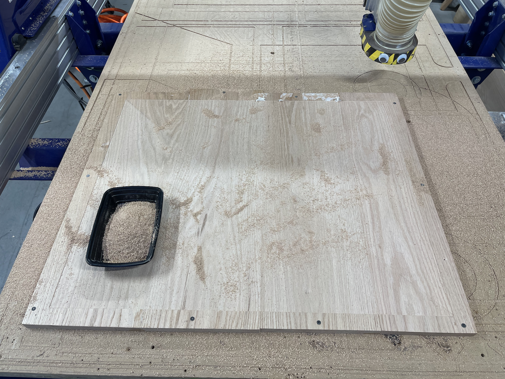
Fig. 11: Note the un-faced offcut border; as noted, that’s why we make our board a bit bigger than we need, so we can bolt down and eventually cut that bit off.
Now, the moment of truth – carving the inlay channel! Since we just told the ShopBot to face our board down to a constant depth, we know it’s perfectly flat and ready for an inlay channel as long as we don’t unfixture the board. I’ll use the same pattern that I carved the brass with (just not reversed this time), but this time I’ll add an extra tolerance in the pocket cut to make the channel just a tiny bit (1/100″ or less) bigger than the brass we’re going to insert, so the brass slides in nicely. VCarve (the software we commonly use at Resistor to define ShopBot toolpaths) has a pocket tolerance that does exactly this (it also has ‘automatic inlay settings’ which didn’t make a good fit at all for me the one time I tried them – more effort on my part needed there, but for now I’ll stick to doing it manually). I’ll also drop my inlay down 1/32″ or less below the surface of the wood, so I can grind the whole thing down for a perfect, mirror smooth tabletop at the end.
All of which sounds great – until I started my channel cut, and got this!
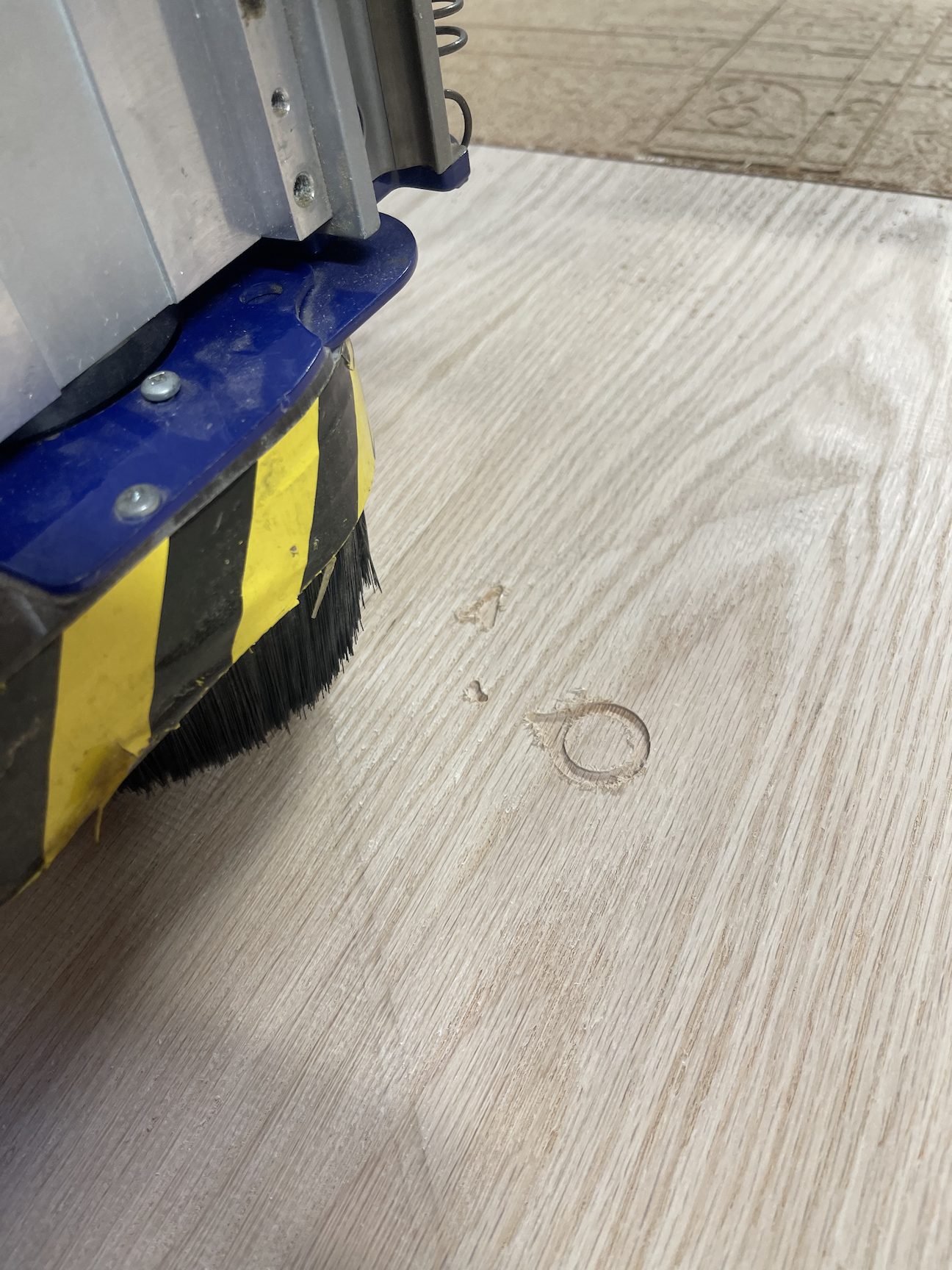
Fig. 12: crap wtf that’s not what I drew on the computer D:
Did I mess up my vector file? Did I not specify my toolpaths correctly? Do I not know what a zig-zag is? Trying not to panic and conclude that I was on my way back to the lumber yard to start all over, I watched the ShopBot skip around, pecking at my perfectly level tabletop until the desired pattern emerged more or less perfectly (modulo some fuzzy edges I cleaned up by hand with a file) – the moral of the story being, CAM software picks weird toolpaths sometimes that only make sense to robots fitfully dreaming; let it do its thing and you’ll (probably) get the cut you set up. Once you’ve got the channel routed out, try popping in the brass (this is why we cut the brass first) – if it doesn’t fit, you can increase the pocket tolerances by a few 1/1000″; if the brass sits up above the surface of the wood, drop the channel down another 1/100″ at a time until the brass completely sits in the channel and under the wood plane. At this point, if you overdid it on the pocket tolerances, you can mix that tray of sawdust you kept with a bit of wood glue and mush the resulting paste into the cracks with your finger (the same trick works along the glue-up seams, too); since the sawdust came from the same wood, the color will match perfectly and you’ll have a near-invisible seam, and a raw inlay that looks like this!
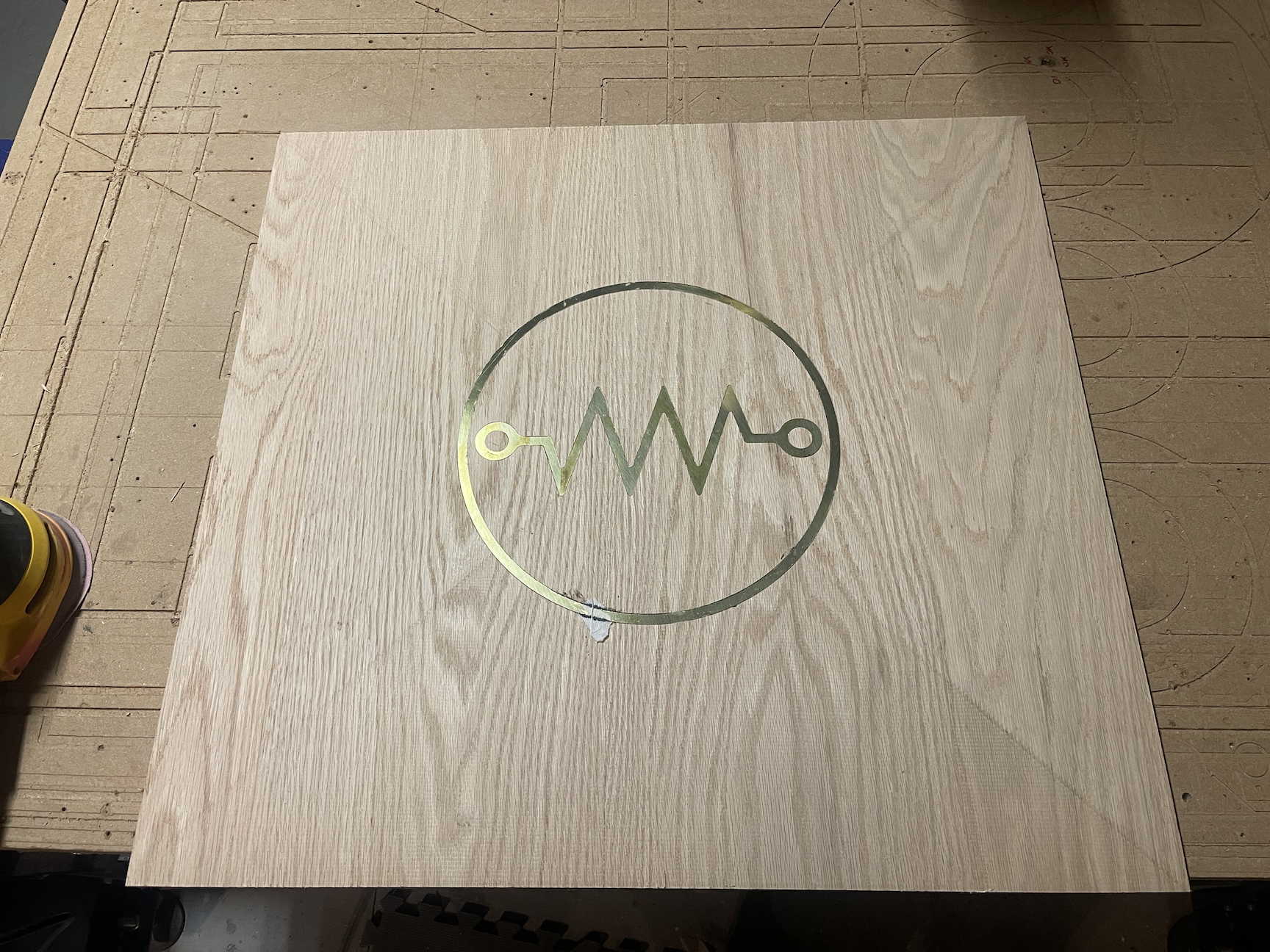
Fig. 13: we did it! Mostly. The paper schmutz was left over from gluing the brass in, covering it with a paper towel, and squashing it overnight with a big slab of granite; it’ll grind off easily. Also note the X shaped machining pattern left by the ShopBot – another thing for the orbital sander to chew through.
Sealing and finishing
We’re almost there! The high-risk parts of the project are complete; all that’s left is to finish the surface and seal the wood. As noted above, our brass should be sitting a tiny bit below the surface of the wood at this point; I used an orbital sander stepping up from 80-120-220 grit to level and smooth out the surface. Of course, this will obliterate the mirror finish of the brass plate we polished above (which I mostly did just to see if I could), but if you’ve got your inlay edges perfectly flush, you can re-polish in the same way to restore the shine if desired.
The last step is to seal the wood with some sort of sealant that will prevent moisture exchange and warping long term. I use some flavor of polyurethane for this; there’s a wide variety of glosses, bases, and other parameters you can experiment with to taste, but I like high-solid semigloss oil based poly for its hard finish and ease of application in fewer coats. I furthermore like to cut my poly 4:1 with mineral spirits; this helps reduce the number of streaks and bubbles in the poly surface.
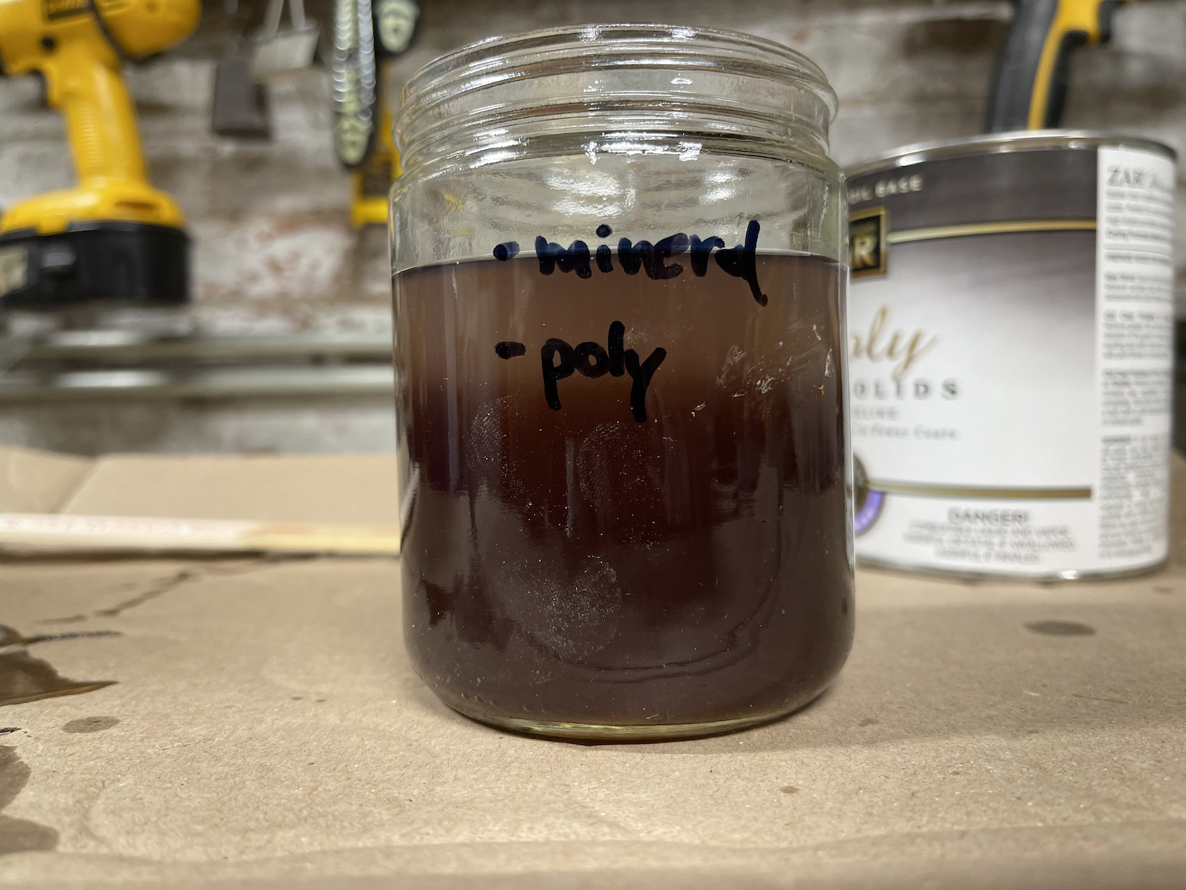
Fig. 14: fortifying polyurethane cocktail, garnish with foam brush to taste.
Finally, when applying your poly coats, start with the underside first, and apply in long, straight stokes, all in the same direction, with a fresh foam brush, go straight over the brass without stopping, and critically, resist the urge to go back over spots and try to touch up streaks / gaps / bubbles. You will only make it worse. Polyurethane, even cut with mineral spirits, starts to harden so quickly that all those extra brush strokes will be preserved as a monument to your polyurethaning sins forever. Do the best you can with the straight strokes, and if it isn’t perfect, give the surface a light, by-hand sanding with a 220 grit paper, and try again; you’ll almost never get a perfect coat the first time (outgassing from the raw wood pretty much always makes bubbles on the first go), but within two or three coats, you’ll have a beautifully inlaid and sealed tabletop:
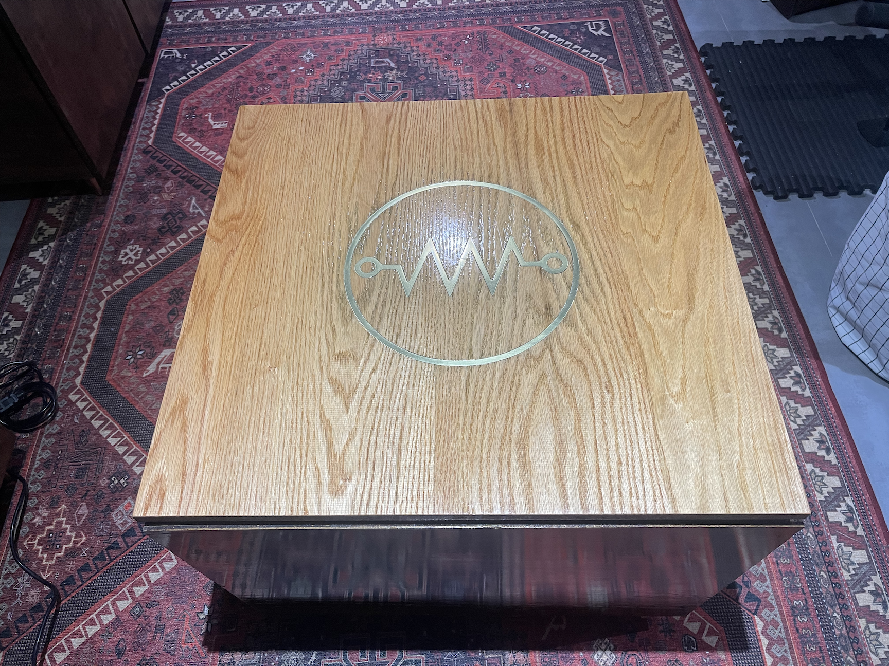
Fig. 15: huzzah! And before anyone asks about the rest of the owl, the base I attached this to is literally just a pine box, nothing too fancy there. Will probably redo that part when I figure out cabinetry.
Victory!
There we have it – one successfully inlaid tabletop from the mostly-guessing school of artistic woodworking and machining. This was actually the final piece in a series of three consoles and two tabletops, but what’s enumerated above is the distillation of what I learned over a year of playing around with this and a lot of help from other Resistors. As noted, this was more or less my first solo woodworking and CNC story arc ever – if there’s a slightly less deadly-power-tool-intensive craft you’ve always wanted to try, I hope you’ll join us on Craft Night at Resistor every Monday and Thursday night, and take a swing at it with us.
Sorry, the comment form is closed at this time.