Robot Army
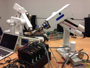
A friend recently acquired a set of PUMA 260 / RP Automation robot arms and asked for some assistance in getting them running again.
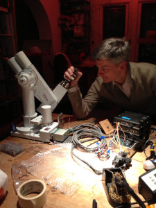
Unfortunately they had been removed from their previous occupation with a set of wire-cutters. Some wires were labeled, most were not. But after a few weekends with a multimeter and some oscilloscope work, we have it running again. Read on for how to bring these arms back to life.
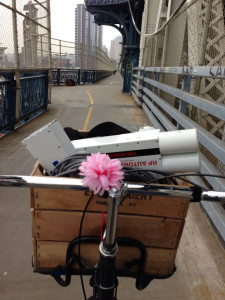
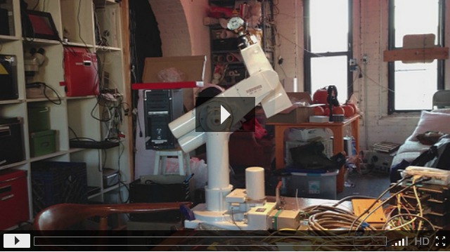
First we had to transport it to NYCR for hacking. One robot arm, power supply and motor controllers just fit in my bike basket. 30kg is a hefty weight to haul over the Manhattan bridge. I’m glad he didn’t have the PUMA 560 arms.
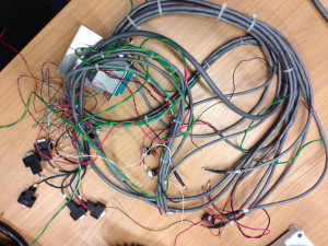
The wiring harness had the cables in several bundles, so it was fairly easy to figure out what most of them did. The quadrature encoders are +5V powered via the axis #1 input on pins 8 and 9 of the attached DB9. All axes share the common power supply and have the normal two quadrature outputs on pins 1 and 4. Pin 6 is used for an index pulse — each axis will trigger a pulse about twice per revolution, allowing the controller to detect an absolute position if it has an estimate of the starting point.
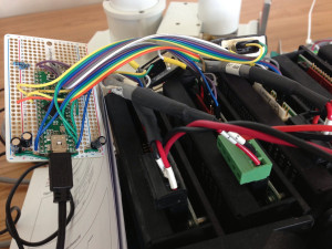
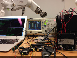
The arm included a beefy 50V DC power supply and a few working (and a few burnt out) Copley 403 h-bridge motor drivers with a maximum output of 5A. These motor amps do not have any position feedback, so I built a Teensy++ based controller that used interrupts to decode the quadrature and index pulses, and generated the analog voltages via PWM and filter caps to command the motor controllers. The input is a differential from an arbitrary reference, so I used a voltage divider to make 2.5V and avoid the need for a negative supply.
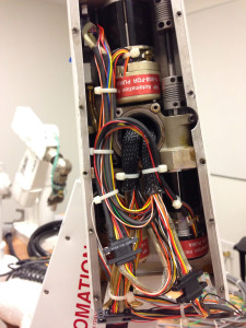
I started with the three axes in the forearm since they are the least likely to cause death and dismemberment, and because they could be commanded without needing to release the brake. Each axis has a DC motor with the quadrature encoder and index pulse built onto it, multiple shaft alignment couplers and a gear train to drive the axis. There are mechanical stops, but no limit switches, on each axis. It seems that these could be removed for the last three since there are no wires going through the final mechanical stages of the wrist.
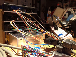
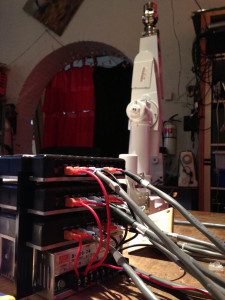
Since we needed new motor controllers to replace the burnt out ones, it was less expensive to buy three new RobotEQ MDC2250C controllers, which also include quadrature decoders and PID position controllers. This makes the board I built redundant, but is far less soldering overall. I rewired the harness to use the lugs and have temporary connectors on the quadrature inputs. For power I’m using a small MeanWell S-320-24, 24V @ 12A supply.
The MDC2250 doesn’t support the index pulse homing natively, so there will need to be some outer-loop control that monitors the pulse on the index pin to zero the arm. Until then the power-on state is in a straight-up position aligned with witness marks made by the previous owner.
Configuring the RobotEQ over the serial port is done with a text protocol documented in their user manual. While in open loop mode it is vitally important to verify that the encoders are generating inputs and that they are moving in the same direction as the motor. To do this, run these commands:
?C
!G 1 100
!G 2 100
!G 1 0
!G 2 0
?C
The output in response to two motor impulses should cause a positive change in two counter values since the motor has been driven in a positive direction. If the count goes negative you can fix it by swapping the two quadrature inputs. Do not enable closed loop control until this is verified! Otherwise the motors can run away and damage the arm.
The main commands are EMOD to select the encoder mode (18==encoder 1 feeds into motor 1, 34==encoder 2 feeds into motor 2), MMOD to select the position control mode (3 == position command), MVEL to configure the maximum velocity. The RWD will disable the watchdog — otherwise the controller will return the encoder to 0 after one second.
^EMOD 1 18
^EMOD 2 34
^MMOD 1 3
^MMOD 2 3
^MVEL 1 10000
^MVEL 2 10000
^RWD 0
If the motor hasn’t started oscillating immediately, you can now try to send a motion command:
!P 1 1000
If all goes well, you can start to send commands to all six axes simultaneously!
However, you might need to adjust the gains if the arms oscillate. For now we’ve found that low P, zero I and zero D works best:
^KP 1 10
^KP 2 10
^KI 1 0
^KI 2 0
^KD 1 0
^KD 2 0
There is no query command for the serial number of the controller, and the suggestion to use the CANbus ID requires a controller with CAN. Instead we’re using the Analog Center command (ATCR) to encode the mapping to arm axes.
Assuming everything is no working, go ahead and save the EEPROM values:
%EESAV
After all the wrestling, I think we can declare success! Up next, we’ll be working on a library to talk to the motor controller and an Inverse Kinematics library, possibly based on OpenRAVE.
Update (2013-05-12): Inverse kinematics now works! Check it out for full linear motion control of the PUMA arm.
super good! thanks for the step by step guide!
The metal U shaped bracket at the base of the arm was called a nest. It was the starting location for the arm to determine calibration. A simple movement of joint 2 would bring the arm out of the nest. One clear each joint move until it got a index pulse form the encoder.
These are PUMA 260 ‘A’ arm made by Unimation. from the 1980’s. Later there was a PUMA 260 ‘B’ arm that had slightly different covers on the motors. Today Unimation is owned by a Swiss company Staubli. The PUMA arms were replaced by the RX series which has in turn been replaced by the current TX series of six axis arms.
RP Automation was given to rights to continue to support the PUMA series of arms once they became obsolete (Staubli defines Obsolete as more then 7 to 10 year after the last production run).
I worked on these robots when I first started with Staubli almost 18 years ago.
Hi James
I really doubt 5 years later you will get this but… I am trying to get a puma 560 up and running. My Unimate/Unival controller won’t fire up so I am looking at doing everything from scratch. Any chance you might know where I could find a pinout for one of these?
Any help would be appreciated.
thanks
Alan
Hi Alan,
Any chance you’re still fiddling with your 560?
Give me a shout.
Chris Miller
RP Automation Inc.