ATTiny10 programming
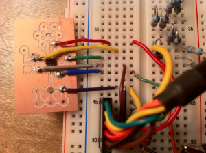
Using Darrel Tan’s Programming the ATTiny10 instructions and a SOT-23 breakout board by Raphael, I was able to flash one of these very small MCU chips. Given the small package, these programmable devices can be dropped just about anywhere on a circuit that a transistor would be used.
Unlike Tan, my FTDI breakout cable does not have DTR, so the reset pin on the chip needs to be pulled low manually to put it into programming mode, and the pinout adjusted. Full instructions after the break…
TXD (Orange) --///--+
                      |   +----------------------+
CTS (Brown)  ---------+---| TPI DATA (1)   RESET | ------+
GND (Black)  -------------| GND              VCC | ---+  |
RTS (Green)  -------------| TPI CLK           NC |    |  |
                          +----------------------+    |  |
                                                      |  |
VCC (Red)    -----------------------------------------+  |
                                                        |
GND (Black)  ---------   -------------------------------+
In /usr/local/etc/avrdude.conf add:
programmer
  id    = "dasaftdi";
  desc  = "tiny10 no reset, sck=!rts mosi=!txd miso=!cts";
  type  = serbb;
  reset = ~4;
  sck   = ~7;
  mosi  = ~3;
  miso  = ~8;
;
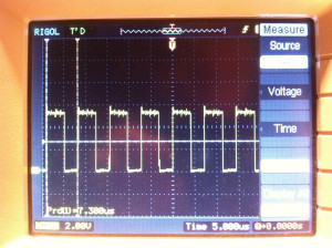
Test program to generate a square wave output on pin D2. My version of avr-gcc doesn’t support the ATTiny10, so I’ve hardcoded the register assignments and pass in the wrong device name to the compiler.
#define DDRB2 2
#define DDRB 0x01
#define PORTB 0x02

.global main
main:
        ldi r16, (1 << DDRB2)
        out DDRB, r16

loop:
        ldi r16, (0 << 2)
        out PORTB, r16
        nop
        ldi r16, (1 << 2)
        out PORTB, r16
        rjmp loop
Compile and generate an Intel hex file:
avr-gcc -mmcu=attiny11 test.S -o test.elf
avr-objcopy -O ihex test.elf test.hex
Manually pull the reset line to ground and flash with this command (substitute the correct path to your FTDI device:
avrdude
  -p attiny10
  -c dasaftdi
  -P /dev/tty.usbserial-FTE531WL
  -U flash:w:test.hex
If all goes well, release the reset line and put a scope on pin 4. You should see something like this:
thanks for posting this, I’ve got some attiny10s on the way so will see how it goes!
could you share what avrdude’s response was? I’m getting
avrdude: Calibrating delay loop… calibrated to 306 cycles per us
program enable instruction not defined for part “ATtiny10”
avrdude: AVR device not responding
avrdude: initialization failed, rc=-1avrdude: AVR device initialized and ready to accept instructionsavrdude: Device signature = 0x000000
avrdude: Yikes! Invalid device signature.
avrdude: Expected signature for ATtiny10 is 1E 90 03
avrdude: NOTE: FLASH memory has been specified, an erase cycle will be performed
To disable this feature, specify the -D option.