Robot arms: now with inverse kinematics
As a followup to our reverse engineering and configuration of 6DOF PUMA robot arms, we’ve updated our controller source code to have full closed form inverse kinematics support. The math is based on A Geometric Approach in Solving the Inverse Kinematics of PUMA Robots, by Lee and Ziegler (1983). Due to the configuration of prismatic and rotational joints in the PUMA arms, it is possible to derive a two part direct trigonometric solutions to the IK problem for this type of arm.
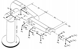
The IK solution uses the DH Parameters to compute the three joint angles for the major axes (the rotation around the stalk, the upper-arm angle, and the fore-arm angle) such that the center of the spherical joint will be placed at a given XYZ position. There are two binary additional binary parameters for this configuration: RIGHT/LEFT controls the orientation of the arm on the right or left side of the stalk, and OVER/UNDER for the configuration of the elbow pointing up or down. See figure 5 in the paper for a diagram of the four possible combinations of these two parameters.
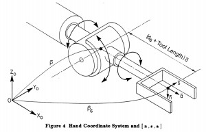
Once the first three theta angles are known, the second phase of the IK solution computes the last three wrist joint angles given the third binary parameter UP/DOWN, and three vectors: the “approach vector” a[] that points in the direction of the tool, the “sliding vector” s[] that points in the direction of the grasping joint, and the “normal vector” n[] that points towards the top of the tool. Figure 4 from the paper shows the relationship of these three vectors in the hand coordinate system.
This video shows the IK iterating between two points (in RIGHT and OVER mode) and generating a piecewise linear path that holds the tool (a cheap pen) mostly level on a constant heading aligned with the X axis. It is a little jerky since the motor controllers don’t have a way to chain commands between points and my calibration on the joint lengths and angles isn’t perfect. Also note that the wrist joints are cross-coupled and require proportional adjustments based on the other joints positions, so the code has some fudge factors to try to account for this behaviour. There are also some corner cases to be sorted out when the “best” joint angles switch quadrants, which will swing the tool around in a circle.
The code isn’t super clean and can use some refactoring to move the DH parameters into a config file, but hopefully you’ll enjoy the human readable code compared to the machine generated ikfast output.
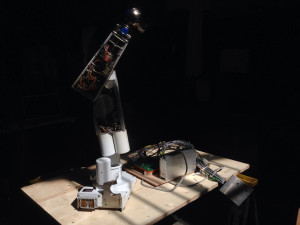
It’s a nice job to work on “retrofitting” this pretty little machine, isn’t it?
We are doing the same in these very days at our university lab, using EtherCAT enabled servo drives. We have found a lot of useful data for kinematics calibration within RCCL, which is still available here: http://www.cs.ubc.ca/~lloyd/rccl.html
Check the files /lib/generic/robotData/puma260.jls/.kyn/.pos..
We have also extracted some data from the memory of the original Unival controller that we have (actually still working!) and they fit very well with those of RCCL..
Check also that the last joint of the wrist is coupled with the previous TWO, not only the previous one..