AVR RFID Multipass
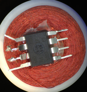
I was inspired by Beth’s avrfid.S project to try to build a replacement for the multiple HID Prox cards that I carry for work. Her design is simultaneously a technical tour-de-force and an example of how badly we can abuse the Atmel chips. Here is the entire schematic:
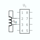
There is no connection to power and ground: the chip is powered through leakage current from the input pins. The AC waveform is fed directly into the pins: the internal protection diodes rectify it. During negative parts of the wave the silicon die’s inherent capacitance maintains state. The CPU clock is driven by the AC as well and depends on the ability of the coil to drive more current than the chip when DDRB is configured to pull the pins to the same potential. It’s truly amazing that this works at all.
The firmware she wrote in macro assembler is easy to understand and straightfoward, but filled the entire 8 KB flash on the ATTiny85 when compiled for HID Prox cards. Unlike the CW modulated EM41xx cards that just load the coil for thirty RF cycles to send a baseband one and don’t load the coil to send a baseband zero, the HID cards use Frequency Shift Keying (FSK) modulation. In FSK a baseband zero is sent by cycling the load on the coil for 50 cycles at a frequency of 4 RF cycles, and a baseband one is sent by cycling the load every 5 RF cycles. Beth’s code loads the coil by setting the two bits in DDRB to 1 while holding PORTB at 0, which places a short across the coil by putting both ends at the same potential.
While it turns out that my dream of automatically selecting the right RFID card doesn’t work, read on for details of how to build your own HID compatible RFID devices and some overview of the hand-tuned assembly necessary to fit the RFID timing.
Instruction timing
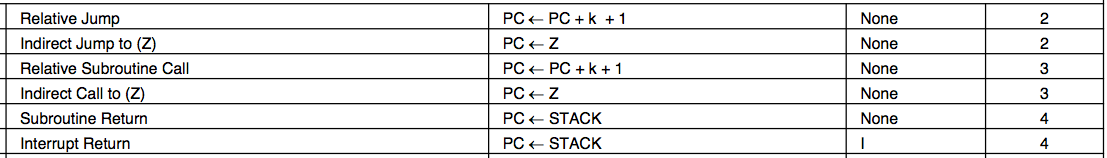
One issue with programming HID Prox compatible cards is that the AVR’s RCALL and RET instructions are quite slow — 3 and 4 clocks respectively — so making a function call and returning from it requires seven clocks and would cause errors in the RF waveform. To get around this, Beth expanded all of the code inline to produce a single function that bit-bangs the coil loading with NOP‘s between each cycle. The 20-bit manufacturer ID (0x01002), 8-bit faciity code and 16-bit unique ID, all Manchester encoded, required 80 instructions per bit for a total of 3700 instructions out of the Tiny85’s maximum of 4096. Supporting 34-bit cards would not be possible with this design, much less multiple card IDs!
While RCALL/RET are out of the question, I noticed that IJMP is only 2 clocks. This means that the CPU can do an indirect jump to the value in the 16-bit Z register in enough time to be ready for the next FSK cycle. If we know where to go, that is… The LPM instruction takes three cycles to read a byte from flash into a register, which just barely fits during the idle time during a FSK baseband one. Loading the Z register for LPM takes at least two clocks (since it is really the two 8-bit registers r31:r30), which means the pgm_read_word() macro in avr/progmem.h won’t work. While the rest of the firmware is in mostly normal C, I resorted to writing assembly to interleave the coil toggling with the operations to determine the next output state and make the appropriate jump. If you want to follow along, the source for the RFID firmware is available in rfid/avrfid2.c.
The state machine
The card IDs are stored in a flash memory character array where the ASCII characters encode the states. 2 is the state that sends the HID header, state 3 is to jump back to the start, and states 0 and 1 send a zero or one. For one of my test cards, the array definition looks like this (with __used__ to indicate to gcc that this array must be present, even if it does not see any usage of it):
static const char hid_bits[]
PROGMEM __attribute__((__used__)) =
{
        "2"                    // HID_HEADER
        "00000001000000000010" // HID code 0x01002 for n1002 cards?
        "00101010"             // Site code 42
        "0101110110001010"     // ID 23946
        "0"                    // parity (should be a separate state)
	"3"                    // HID_RESET
};
The code to send a baseband one looks roughly like this, with the FSK generation interleaved with reading the next state from the hid_bits[] array and then looking up the function to call from the state_handlers[]. At the end of the function, the Z register holds the function pointer to be called next. The toggle macro takes two clocks and turns the load on the coil if it is currently unloaded, or turns it off if it is currently on. This leaves three clocks to do before the next toggle. Most of the instructions are single cycle, except for LPM which is three clocks, and RJMP .+0 which is a two clock NOP.
baseband1:
	toggle /* 5 */
				ldi r30, lo8(hid_bits)
				ldi r31, hi8(hid_bits)
				add r30, r15 // bit_num
	toggle /* 10 */
				lpm r24, Z // next_bit = lpm(hid_bits[bitnum])
	toggle /* 15 */
				ldi r30, lo8(state_handlers)
				ldi r31, hi8(state_handlers)
				nop
	toggle /* 20 */
				subi r24, '0'
				lsl r24
				add r30, r24 // z = &state_handlers[next_bit - '0']
	toggle /* 25 */
				lpm r24, Z+
	toggle /* 30 */
				lpm r31, Z
	toggle /* 35 */
				mov r30, r24 // z = lpm(z);
				rjmp .+0
	toggle /* 40 */
				inc r15 // bit_num++
				rjmp .+0
	toggle /* 45 */
				nop // Nothing to do!
				rjmp .+0
	toggle /* 50 */
				/* Leave last delay slot free */
Flashing the RFID
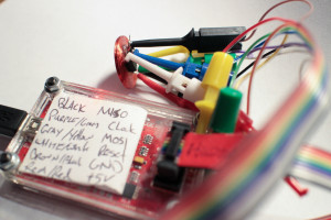
Once the fuse bits have been configured to use the RF waveform as the clock source the chip will no longer be programable with a normal AVR ISP. One option is to use Dangerous Prototypes’ buspirate, which can provide a “recovery” clock during programming. Unfortunately it didn’t work for me with the current release of avrdude; I had to make the following patches to the avrdude/buspirate.c source to get it to work. The pinout to connect the Tiny85 to the buspirate:
                        +-------+
    White/white   Reset |1  v  8| Vcc   Red
    Blue/Blue     Xtal1 |2     7| SCK   Purple/green
                  Xtal2 |3     6| MISO  Black/Black
    Black         Gnd   |4     5| MOSI  Gray/Yellow
                        +-------+
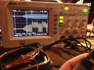
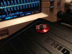
Testing the RFID
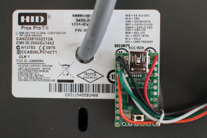
To better test my design, I needed a way to read the HID cards. Unfortunately the commonly available RFID readers from sparkfun and adafruit only read EM4xxx cards, not the HID Proxcard modulation. So I acquired a surplus HID ProxPro II and built a small adapter with a Teensy 2.0. The output of the device is an odd format — Wiegand transmits zeros on one wire and ones on the other — so it required adapting to connect to a normal computer. My rfid/hid-rfid-reader.c program translates this into an easy to parse serial output. Each output line is a complete read of a card in ASCII formatted binary.
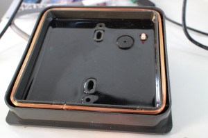
If you wanted to try to modify the firmware of the reader, you’re out of luck. There are no user servicable parts inside — the entirety of the body is filled with potting compound epoxy. If you’re interested in lower level details and compatibility with multiple card formats, the proxmark3 is a better device for further hacking.
Unfortunately it turns out that my dream of cycling through multiple IDs won’t work with the way HID Prox readers report their results. They seem to query the card continuously until they receive two identical reads of the ID, then they stop probing until the reader detects that the card has left the field. This means that cycling continuously between IDs will cause it to never read any of them, and cycling between two repeats of each cards will cause it to stop reading after the first duplicate read succeeds. There are enough pins on the Tiny85 (or even the microscopic Tiny10) and plenty of space left if I wanted to add a switch to select between different IDs, but this would require me to remove the device from my pocket, which would somewhat defeat the purpose of the multipass.
Oh well… It was a mostly successful and very fun project, and an exciting challenge to fit everything in such a small device. Thanks so much to Beth for the source code and documentation on the various protocols.
Update (2013-11-18): The firmware now supports the HID Corporate 1000 35-bit format for more modern cards.
I have done your exact work 2 years ago (replacing rcall/ret with ijmp, and trying to implement multiple IDs on the Tiny85) 😀
Like you I found out this limitation of the HID readers…
Could you break the coil with a jfet so that it no longer is detected by the reader?
How about a badge with membrane switches to select witch code to use.
and one set of pads to short for programming new codes.
have you considered breaking the coil into multiple segments in order to fool the reader into thinking it’s been removed? I’m thinking a jfet shorts the coil’s midpoint into another avr pin. That should allow you to maintain power during that phase, allowing you to time the blackout and maintain state.
would a j fet have any advantage over a depletion mode n channel mosfet?, did you ever try this?
Have you tried adding a small button cell and having the chip send out an in-phase carrier wave to make the reader think you’ve left the field? I wonder what their timeout is.
Look at all those unused pins. Is it possible to read a sensor, e.g. a gyro, and depending on the tag’s orientation select a number?
Maybe there is an Android/iPhone solution to be had here as part of an integrated system.
How much flash does your trimmed code use now? Making this with an Attiny9(10) sounds like an awesome idea, but with only 1k of flash it may not fit?
The final program for HID Prox cards used 846 bytes of code on the Tiny85, down from nearly 7 KB in the original version. I haven’t looked at the instruction timings on the Tiny9/10; you might need to adjust the timing on the state machine that implements the FSK.
How did you make the coil? I was curious about wire size and amount of turns.
What were the correct fuse settings for this? I’d rather not have to mess around with changing those when the fuses can make it that much more difficult to program.
I know, this is an ancient thread. Anyway, I got a variant of this to work by storing an index in eeprom and stepping through the stored codes, so that each time the tag is read it returns the next code. I only have two tags anyway (apartment and work), so it’s not too much of a hassle to have to present it to the reader twice.
Programming the eeprom at such low power levels is a little tricky.