AlphaWatch
I found Matt Joyce’s HDSP211x alphanumeric displays in the LED bin at NYCR and loved the StarTAC style. He had previously written about driving them, but using an Arduino and a shift register on a breadboard was a bit large for my goal of making it into a wristwatch.

I noticed that the PDIP spacing was the same as the Teensy 2.0 and, much like my ROM dumper, hoped that it could fit on the back of the display with almost no additional wires. Read on for the “schematics” and source code details.
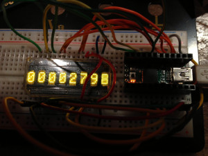
Even though Teensy’s are cheap, I wanted to be sure that the LED modules worked and that I understood the datasheet from Avago Technologies. So that called for a breadboard and the 8 data, 5 address, and four control lines to be jumper wired in place and some test code to be written. After a few mistakes (!FL must be pulled high, since we’re not writing to flash, !WR must be pulled low along with !CE to send commands, and the character RAM at 0x18 | ADDR will write to the display), I had it printing the hex values of a incrementing uint32_t.
I had hoped that the power and ground pins on the Teensy would line up with the ones on the display, but unfortunately they are in the wrong arrangement. After trying all the possible orientations I came up with one that reduced the number of extra jumpers. Pin 2 of the teensy (B0) connects to pin 28 of the display as you can see in the second photo.
The only additional wires are for the two grounds (logic and LED, pins 15 and 16), the combined !WR+!CE line (pins 17 and 13) and +5V (pin 14). I added an extra one for CLK by accident, but it is not required. The rest of the pins are determined by the position of the Teensy — I had to slide it one pin sideways to avoid connected GND and Vcc.
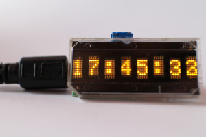
I also soldered a button between pin D1 and ground to allow some amount of user input. Currently it allows toggling between word mode and normal 24h clock mode. Unfortunately I messed up the D2 pad and can’t solder a second button in there.
The full source for the AlphaWatch firmware is available and uses my bits.h library to provide single instruction access to constant IO ports. The mapping of pins to functions is defined at compile time as:
#define ADDR_0  0xF4
#define ADDR_1  0xF5
#define ADDR_2  0xF6
#define ADDR_3  0xF7
#define ADDR_4  0xD7

#define DATA_0  0xC6
#define DATA_1  0xD3
#define DATA_2  0xD0
#define DATA_3  0xB7
#define DATA_4  0xB3
#define DATA_5  0xB2
#define DATA_6  0xB1
#define DATA_7  0xB0

#define FLASH   0xF1
#define RESET   0xF0
#define WRCE    0xD5
#define RD      0xC7
#define CLKSEL  0xD6
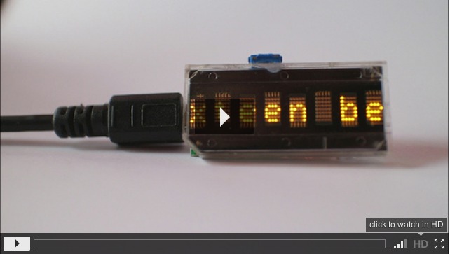
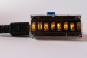
Here’s a short video of the clock in action. It needs some sort of RTC to keep time during power outages and I’m still trying to figure out how to power it for a wristwatch. But it looks great as a deskclock for now and reads out the time in a unique way.
http://dorkbotpdx.org/blog/spacewrench/cool_thing_with_broken_teensy
Great work! I’ve got a 4-character version of that display that I’ve been meaning to make into watch for ages. I’m also stuck with the power problem – it’d be interesting to see what you come up with!
Excellent project. Is there a possibility of receiving schematics and hex file?
!! great build!! I have recuperated about 50+ of those displays from scrap telecom equipment and cisco routers – (12000model line cards), 4 and 8 digits!! I need to do something with them!